Variable speed tooth polishing system
a tooth polishing and variable speed technology, applied in the field of variable speed tooth polishing system, can solve the problems of unstable polishing inconvenient use inability to maintain the stability of existing polisher heads, etc., to facilitate dental care, facilitate the use of dental care, and facilitate the use of the effect of dental car
- Summary
- Abstract
- Description
- Claims
- Application Information
AI Technical Summary
Benefits of technology
Problems solved by technology
Method used
Image
Examples
second embodiment
[0042]Referring now to FIG. 5, a variable speed tooth polishing system 102 is shown with the second polisher 140 replaced by a polisher brush 145. It will be appreciated by those skilled in the art that the prophy angle 105′ of the variable speed tooth polishing system 102 can be attached to other polisher hand grips, and that the first polisher 130 and the second polisher 140 can be removed and either act alone in order to access hard to reach teeth, or be replaced with other variations besides the polisher brush 145, without deviating from the present invention. Another alternative embodiment would entail the first polisher 130 and the second polisher 140 having a plurality of bristles, like those of a toothbrush, or a wide variety of other polishing means without departing from the present invention.
[0043]FIG. 6 illustrates a control unit 300 of the variable speed tooth polishing system 100, 102. The control unit 300 determines the rotational speed of the first polisher 130 and s...
third embodiment
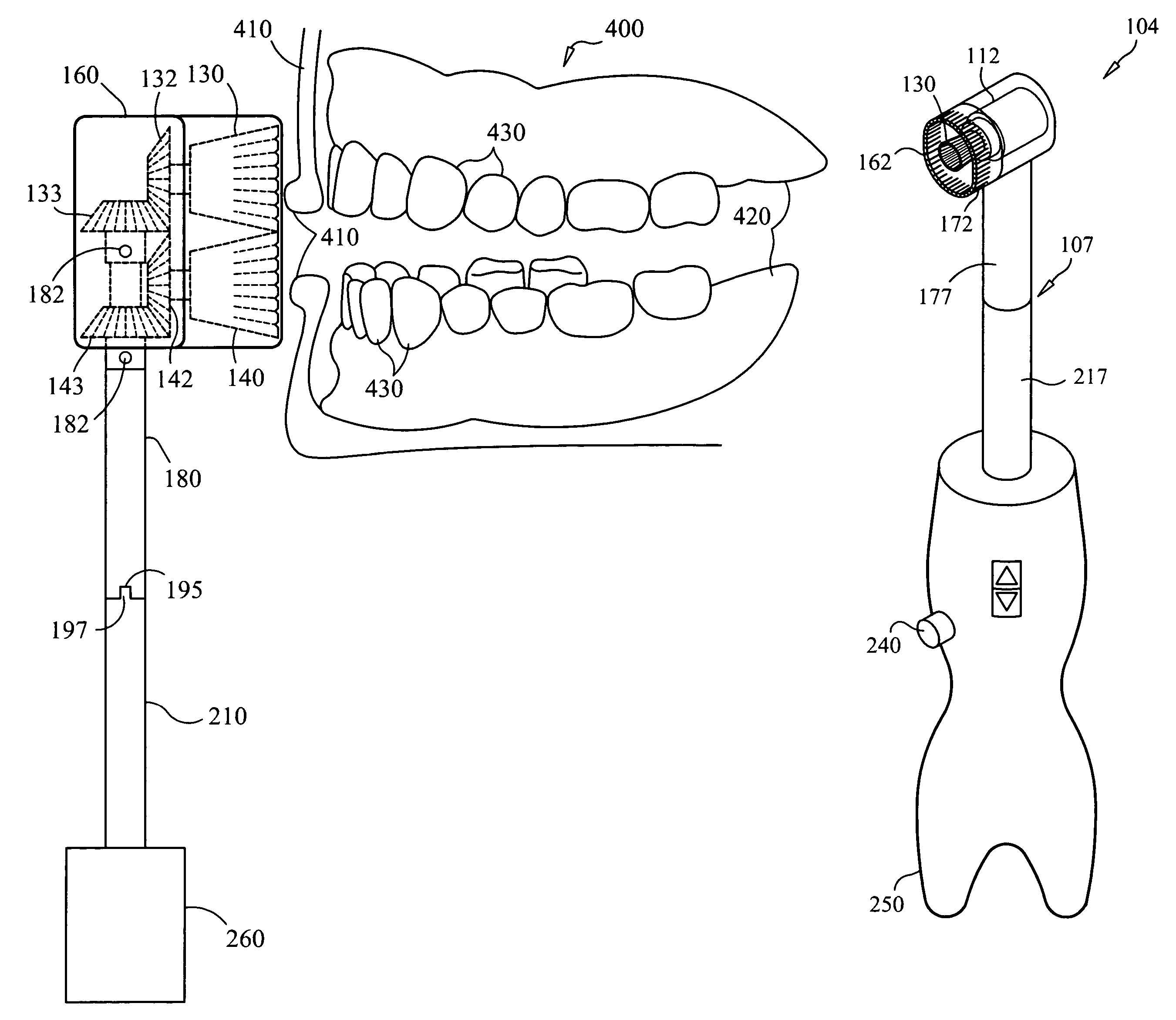
[0044]FIG. 7 illustrates a variable speed tooth polishing system 104 with a single polisher 130. The variable speed tooth polishing system 104 includes a polisher hand grip 250 and a prophy angle 107. A hand grip connector housing 217 extends from the polisher hand grip 250. The prophy angle 107 includes a prophy angle connector housing 177 and a splatter guard 162. The prophy angle connector housing 177 is preferably screwed to the hand grip connector housing 217, but other attachment methods may also be used. A polisher housing 112 is retained in the splatter guard 162. A plurality of splatter slots 172 are formed in a front of the splatter guard 162. The polisher is retained in the polisher housing 112.
[0045]FIGS. 8-10 illustrate a method of attaching a polisher 130, 140 to a polisher gear 132, 142, respectively. An undercut projection 147 extends from the polisher gear 132, 142. A projection cavity 149 is formed in a rear of the polisher 130, 140. The projection cavity 149 is si...
PUM
 Abstract
Description
Claims
Application Information
 - R&D
- Intellectual Property
- Life Sciences
- Materials
- Tech Scout
- Unparalleled Data Quality
- Higher Quality Content
- 60% Fewer Hallucinations
Browse by: Latest US Patents, China's latest patents, Technical Efficacy Thesaurus, Application Domain, Technology Topic, Popular Technical Reports.
© 2025 PatSnap. All rights reserved.Legal|Privacy policy|Modern Slavery Act Transparency Statement|Sitemap|About US| Contact US: help@patsnap.com


