Splash guard of machine tool

a technology of machine tools and blade guards, applied in the field of blade guards, can solve the problems of deterioration of machining accuracy, inconvenient adjustment of blade guards, and inability to adjust, so as to reduce the deterioration of machine accuracy and suppress the bed. the effect of deterioration

Active Publication Date: 2011-06-14
MAKINO MILLING MASCH CO LTD
View PDF11 Cites 8 Cited by
  • Summary
  • Abstract
  • Description
  • Claims
  • Application Information

AI Technical Summary

Benefits of technology

[0007]Accordingly, it is an object of the present invention to provide a splash guard which can reduce the deformation of the bed under the weight of the splash guard installed, without increasing the installation space for the machine tool.
[0008]According to the present invention, there is provided a splash guard of a machine tool, which includes a rear cover mounted on a rear of a bed of the machine tool installed on a floor surface and defining a partition for a rear side of a machining area and a front cover defining a partition, for a front side and lateral sides of the machining area, said rear cover and said front cover surrounding the machining area to prevent coolant and chips generated by the machine tool machining the workpiece from being scattered around, wherein the front cover includes a lower cover placed on the bed of the machine tool and an upper cover placed above the lower cover and wherein the upper cover includes a plurality of legs extending downward from the lower end thereof so that the upper cover, when the upper cover is placed above the lower cover, is supported on the floor surface, by the plurality of legs.
[0011]In the splash guard of the machine tool according to the present invention, the upper cover surrounding the machining area is supported on the floor surface by the plurality of legs, and therefore, the weight of the upper cover does not substantially act on the bed and the deformation of the bed can be suppressed. Therefore, even if the upper cover is placed above the lower cover after the adjustment is made, the deterioration of the machine accuracy can be minimized.

Problems solved by technology

In this process, the splash guard, if covered on the upper part of the bed, is often inconvenient for adjustments.
However, if the splash guard is installed on the bed after the adjustments, there is a problem that the bed is deformed due to the weight of the splash guard and the adjustment is spoiled, resulting in the deterioration of machining accuracy.
However, in the case as described above where the whole machine tool is accommodated within the splash guard larger than the machine tool, the space for installing the splash guard larger than the machine tool is required, thereby posing the problem of an increased installation space.
Since the splash guard is larger than the machine tool, another problem occurs in that the scattered coolant which may run down along the inner surface of the splash guard and may leak out of the machine tool.

Method used


Image

  • Splash guard of machine tool
  • Splash guard of machine tool
  • Splash guard of machine tool

Examples


Embodiment Construction

[0017]A preferred embodiment of the present, invention will be described below with reference to the accompanying drawings.

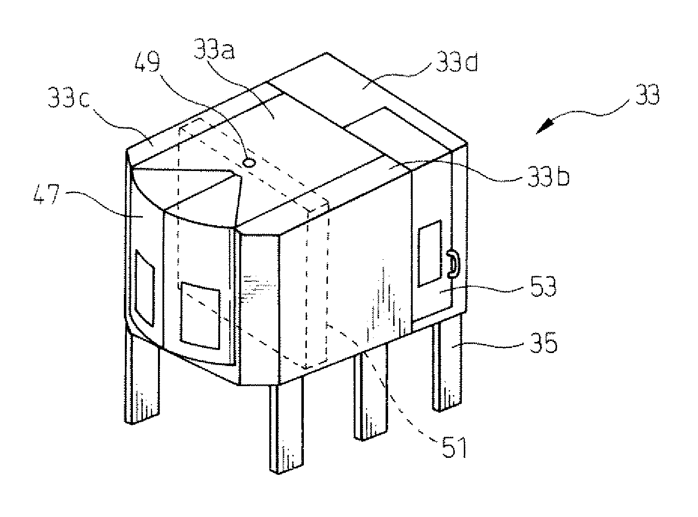
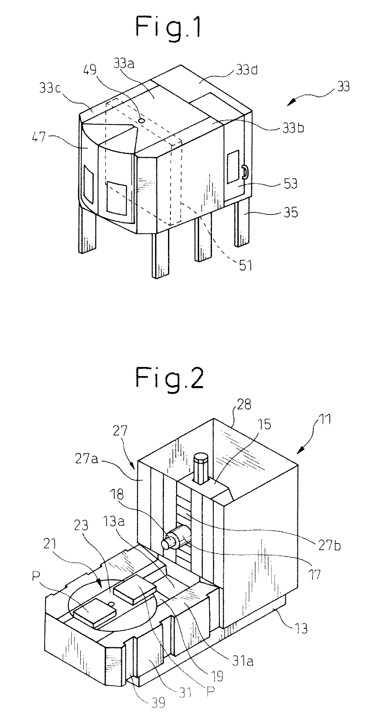
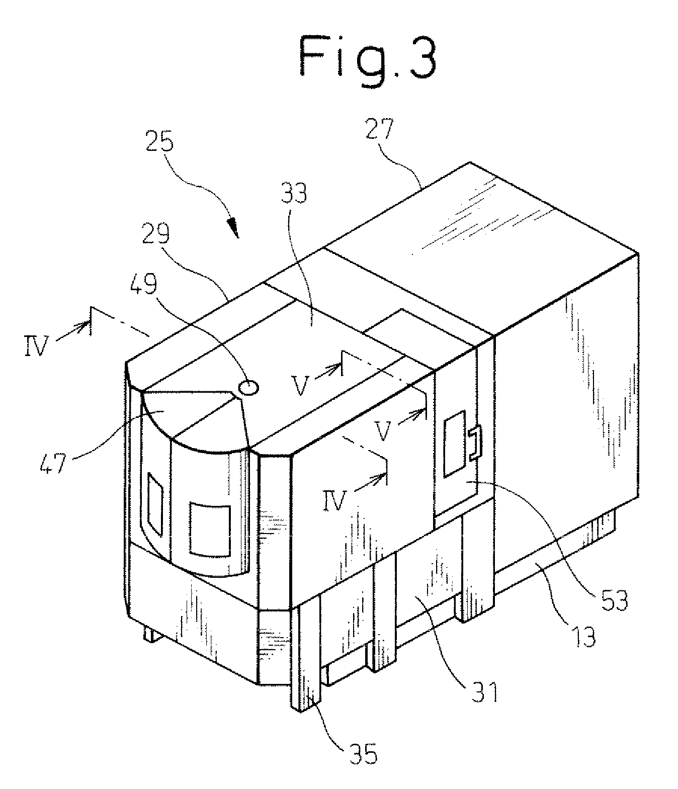
[0018]First, referring to FIGS. 1 to 3, a general configuration of a machine tool using a splash guard according to the present invention will, be described. Although a horizontal machining center is used as a machine tool 11 in the shown embodiment, the invention is also applicable to another arbitrary types of machine tools such as a vertical machining center.

[0019]Machine tool 11 shown in the figures includes a bed 13 installed on a floor surface, a column 15 erected on bed 13 so as to be movable in left-right direction (along X-axis), a spindle head 17 supported by column 15 so as to be movable in vertical direction (along Y-axis), a table 19 constituting a pallet mount provided on bed 13 so as to be movable in front-back direction (along Z-axis) and a pallet changer 21 provided on bed 13 to change a pallet P placed on table 19, and machines a workpiece by m...


PUM

PropertyMeasurementUnit
weightaaaaaaaaaa
areaaaaaaaaaaa
lengthaaaaaaaaaa

Abstract

A splash guard (25) of a machine tool for preventing chips generated when a workplace is machined by the machine tool or coolant from being scattered includes a rear cover (27) mounted on a rear of a bed (13) of the machine tool installed on the floor surface and defining a partition for a rear side of the machining area, and a front cover (29) defining a partition for a front side and lateral sides of the machining area. The front cover (29) is configured of a lower cover (31) placed on the bed (13) of the machine tool, and an upper cover (33) placed above the lower cover (31). The upper cover (33) has a plurality of legs (35) extending downward from the lower end thereof so that the upper cover (33), when arranged above the lower cover (31), is supported on the floor surface by the plurality of legs (35).

Description

TECHNICAL FIELD[0001]The present invention relates to a splash guard for preventing chips and coolant from being scattered when a workpiece is machined by a machine tool.BACKGROUND ART[0002]It is common practice to surround a machining area of a machine tool such as a machining center, a lathe or a grinding machine with a splash guard in order to prevent chips and coolant from being scattered when machining a workpiece. Such a splash guard is often located on the bed of the machine tool so as to surround the machining area in order to prevent the scattered coolant from running down along the inner surface of the splash guard and leaking out of the machine tool.[0003]However, when installing a machine tool, various adjustments are required, including the adjustment for horizontally placing a movable table on the bed and the adjustment for assuring the rectilinear motion of the moving unit in orthogonal directions to each other along X, Y and Z axes. In this process, the splash guard,...

Claims


Application Information

Patent Timeline
Patent Type & Authority Patents(United States)
IPC IPC(8): B23Q11/08
CPCB23Q11/0891F16P1/02Y10T409/30392Y10T74/219
Inventor HARA, KUNIOYAMADA, KENJI
Owner MAKINO MILLING MASCH CO LTD
Why Eureka
Try Eureka