Control for vehicle power transmission system

a technology for power transmission systems and controllers, which is applied in the direction of electric propulsion mounting, machines/engines, and gearing. it can solve the problems of limited torque reduction amount of electric motors, increased engine rotational speed, and insufficient removal of shift shocks

Inactive Publication Date: 2011-06-14
TOYOTA JIDOSHA KK
View PDF7 Cites 13 Cited by
  • Summary
  • Abstract
  • Description
  • Claims
  • Application Information

AI Technical Summary

Benefits of technology

[0007]The invention provides a controller for a vehicle power transmission system that includes an electric differential unit which includes a differential mechanism, having an input shaft and an output shaft, and an electric motor and which allows controlling a differential state between the rotational speed of the input shaft coupled to an engine and the rotational speed of the output shaft by controlling an operating state of the electric motor coupled to a rotating element of the differential mechanism, a transmission unit that is arranged in a power transmission path between the electric differential unit and a drive wheel, and an engine upper limit setting device that is able to prevent an engine torque limitation and a shift shock by preventing the engine rotational speed from reaching a high rotational speed region when the transmission unit is shifting speeds, and that transmits power of the engine to the drive wheel.

Problems solved by technology

However, for example, when the level of charge of an electrical storage device reaches an excessive state of charge in a state where it is impossible to reduce torque by the engine because of a decrease in engine coolant temperature, or the like, a torque reduction amount by the electric motor is limited.
This may cause a situation where a shift shock is not sufficiently removed.
However, when a torque reduction amount by the electric motor is limited as described above, an amount of increase in engine rotational speed increases.
In addition, as the engine rotational speed reaches the high rotational speed region, an electronic throttle valve is closed to limit an engine torque in order to reduce the engine rotational speed, and the engine torque limitation may possibly cause a shift shock.
However, there has been taken no effective measures against the above problem.

Method used


Image

  • Control for vehicle power transmission system
  • Control for vehicle power transmission system
  • Control for vehicle power transmission system

Examples


Embodiment Construction

[0057]Hereinafter, an embodiment of the invention will be described in detail with reference to the accompanying drawings. Note that in the following embodiment, drawings are simplified or deformed where appropriate, and the scale ratio, shape, and the like, of each component is not always drawn accurately.

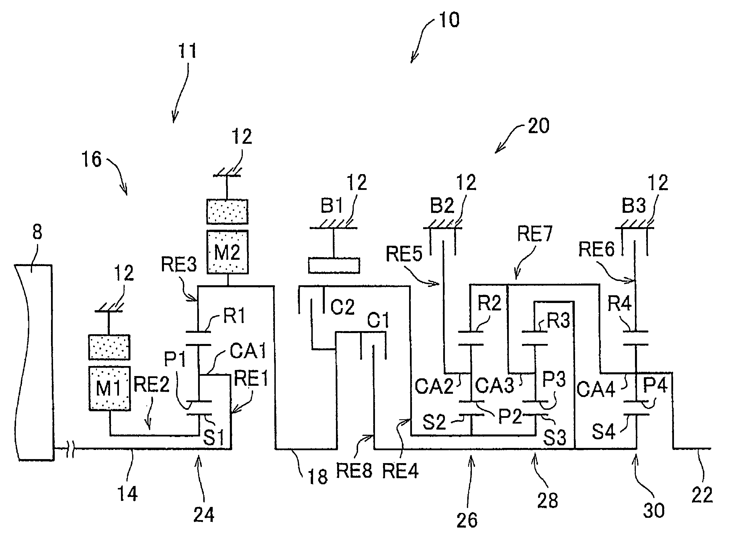
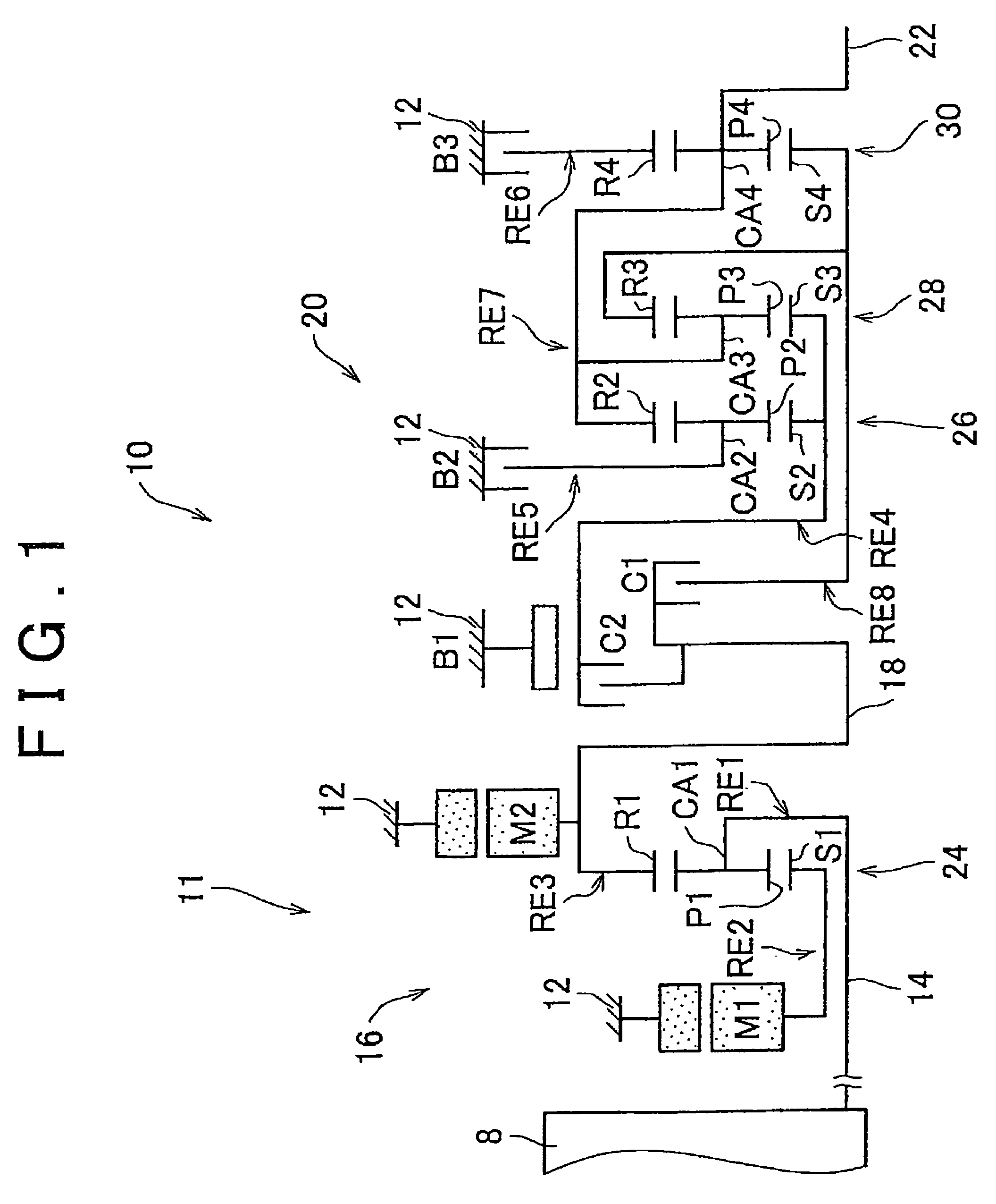
[0058]FIG. 1 is a skeleton diagram that illustrates a transmission mechanism 10 that constitutes part of a power transmission system for a hybrid vehicle according to the embodiment of the invention. As shown in FIG. 1, the transmission mechanism 10 includes an input shaft 14, a differential unit 11, an automatic transmission unit 20, and an output shaft 22, which are coaxially arranged in series with one another in a transmission case 12 (hereinafter, referred to as the case 12). The case 12 serves as a non-rotating member and is secured to the body of the vehicle. The input shaft 14 serves as an input rotating member. The differential unit 11 serves as a continuously variable tr...


PUM


Abstract

A controller for a vehicle power transmission system includes: an electric differential unit that includes a differential mechanism, having an input shaft and an output shaft, and an electric motor and that allows controlling a differential state between the rotational speed of the input shaft coupled to an engine and the rotational speed of the output shaft by controlling an operating state of the electric motor coupled to a rotating element of the differential mechanism; a transmission unit that is arranged in a power transmission path between the electric differential unit and a drive wheel; and an engine upper limit setting device that, when the transmission unit is shifting speeds, prelimits an upper limit of the rotational speed of the engine when the rotational speed of the engine increases because of torque reduction control by the electric motor. With the above control, the rotational speed of the engine is prevented from reaching a high rotational speed region.

Description

INCORPORATION BY REFERENCE[0001]The disclosure of Japanese Patent Application No. 2008-151406 filed on Jun. 10, 2008 including the specification, drawings and abstract is incorporated herein by reference in its entirety.BACKGROUND OF THE INVENTION[0002]1. Field of the Invention[0003]The invention relates to a controller for a vehicle power transmission system that includes an electric differential unit which includes a differential mechanism, having an input shaft and an output shaft, and an electric motor and which allows controlling a differential state between the rotational speed of the input shaft coupled to an engine and the rotational speed of the output shaft by controlling an operating state of the electric motor coupled to a rotating element of the differential mechanism, and a transmission unit that is arranged in a power transmission path between the electric differential unit and a drive wheel, and the vehicle power transmission system transmits power of the engine to t...

Claims


Application Information

Patent Timeline
Patent Type & Authority Patents(United States)
IPC IPC(8): B60K1/02B60K6/445B60K6/547B60L50/16B60W10/06B60W10/08B60W10/10B60W20/00F02D29/00F02D29/02
CPCB60K6/445B60W10/06B60W10/08B60W10/115B60W30/1884F16H61/0437B60W30/19B60W20/00Y10T477/23F16H2037/0866F16H2061/6603Y02T10/6286Y02T10/6239Y02T10/62
Inventor MATSUBARA, TOORUTABATA, ATSUSHIKAIFUKU, MASAKAZU
Owner TOYOTA JIDOSHA KK
Why Eureka
Try Eureka