Robotic devices with agent delivery components and related methods

a robot device and component technology, applied in the field of robot devices, can solve the problems of limited scope and complexity of known laparoscopy technologies, the range of motion of surgeons, and the complexity of surgical procedures being performed

Inactive Publication Date: 2011-06-14
BOARD OF RGT UNIV OF NEBRASKA
View PDF354 Cites 81 Cited by
  • Summary
  • Abstract
  • Description
  • Claims
  • Application Information

AI Technical Summary

Problems solved by technology

However, known laparoscopy technologies are limited in scope and complexity due in part to (1) mobility restrictions resulting from using rigid tools inserted through access ports, and (2) limited visual feedback.
That is, long rigid laparoscopic tools inserted through small incisions in the abdomen wall limit the surgeon's range of motion and therefore the complexity of the surgical procedures being performed.
Similarly, using a 2-D image from a typically rigid laparoscope inserted through a small incision limits the overall understanding of the surgical environment.
However, da Vinci® is still restricted by the access ports.
Further disadvantages include the size and high cost of the da Vinci® system, the fact that the system is not available in most hospitals and the system's limited sensory and mobility capabilities.
In addition, most studies suggest that current robotic systems such as the da Vinci® system offer little or no improvement over standard laparoscopic instruments in the performance of basic skills.
Further, the da Vinci® system and similar systems are implemented from outside the body and will therefore always be constrained to some degree by the limitations of working through small incisions.
For example, these small incisions do not allow the surgeon to view or touch the surgical environment directly, and they constrain the motion of the endpoint of the tools and cameras to arcs of a sphere whose center is the insertion point.

Method used


Image

  • Robotic devices with agent delivery components and related methods
  • Robotic devices with agent delivery components and related methods
  • Robotic devices with agent delivery components and related methods

Examples


example 1

[0180]This example is an examination biopsy tool design for a mobile robotic device. The device should produce sufficient clamping and drawbar forces to biopsy porcine tissue.

[0181]To examine clamping and drawbar forces used during a biopsy, experimental biopsies were conducted. A biopsy forceps device that is commonly used for tissue sampling during esophago-gastroduodenoscopy (EGD) and colonoscopies was modified to measure cutting forces during tissue biopsy. These forceps 280, shown schematically in FIG. 17A, were composed of a grasper 282 on the distal end with a handle / lever system 284 on the proximal end. A flexible tube 286 was affixed to one side of the handle 284 and the other end was attached to the fulcrum point 288 of the biopsy grasper 282. A wire 290 enclosed in plastic (Teflon®) inside tube 286 was used to actuate the grasper 282. This wire 290 was affixed to the free end of the handle lever 284 and at the other end to the end of the grasper lever arm 292. Actuation o...

example 2

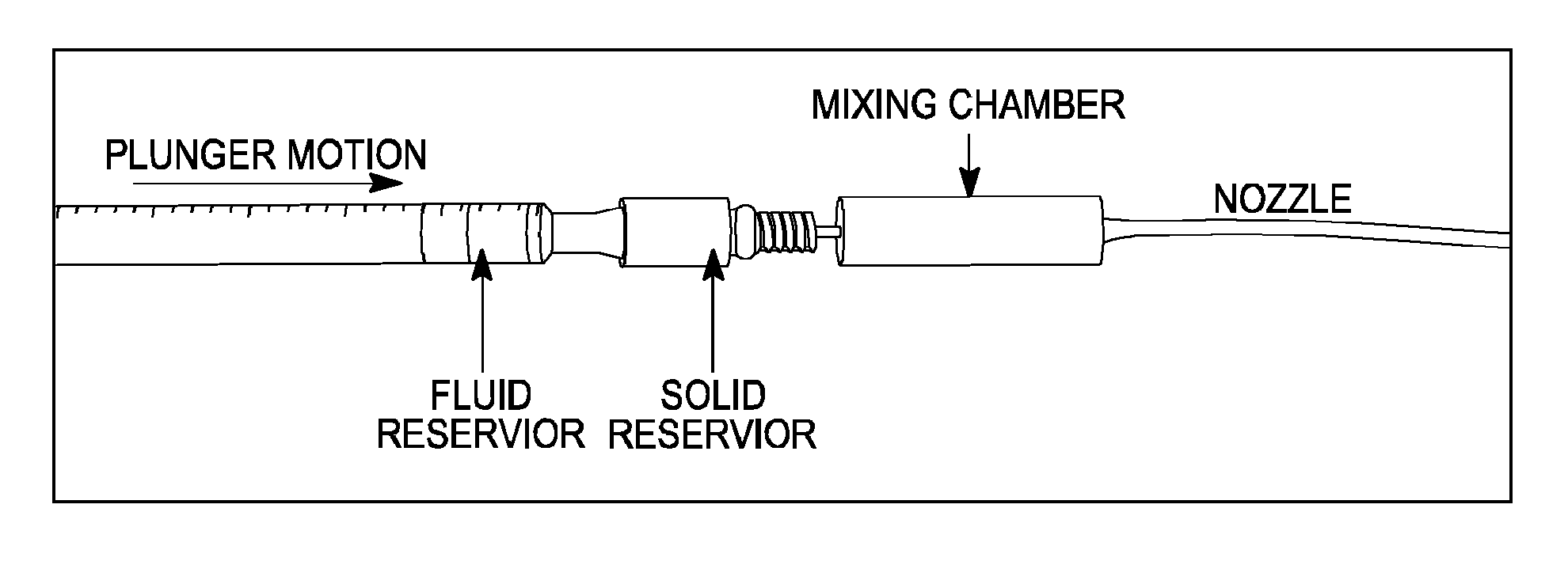
[0198]A laboratory two-component drug delivery system is shown in FIG. 23 that incorporates two drug storage reservoirs. The fluid reservoir, adapted from a standard syringe, is used to hold a drug component in liquid form. The solid reservoir stores a second drug component in powdered form. As force is applied to the plunger, the liquid component flows through the reservoir holding the solid component. A partially mixed solution then flows into a chamber where the mixing process is completed. The activated compound then flows through the delivery nozzle to the targeted site.

[0199]The ability of this system to adequately mix liquid and solid components of a drug was evaluated in a series of bench top experiments. The liquid and solid drug components were simulated using commonly available materials (e.g., corn starch, dyed saline solution, etc). One visual metric of mixing efficiency is the color uniformity of the mixture as determined by measuring the RGB color components of the mi...


PUM


Abstract

Various robotic devices and related medical procedures are disclosed herein. Each of the various robotic devices have an agent delivery component. The devices include mobile robotic devices and fixed base robotic devices as disclosed herein. The agent delivery component can have at least one agent reservoir and a discharge component in fluidic communication with the at least one reservoir.

Description

CROSS-REFERENCE TO RELATED APPLICATION(S)[0001]This application claims priority as a continuation of U.S. patent application Ser. No. 11 / 947,097, filed on Nov. 29, 2007, which claims priority to U.S. Provisional Patent Application Ser. No. 60 / 868,030, filed Nov. 30, 2006 and further claims priority as a continuation-in-part of U.S. patent application Ser. No. 11 / 695,944, filed on Apr. 3, 2007, which issued on Feb. 17, 2009 as U.S. Pat. No. 7,492,116, which is a continuation of U.S. patent application Ser. No. 11 / 398,174, filed on Apr. 5, 2006, which issued on Apr. 3, 2007 as U.S. Pat. No. 7,199,545, which is a continuation of U.S. patent application Ser. No. 10 / 616,096, filed on Jul. 8, 2003, which issued on May 9, 2006 as U.S. Pat. No. 7,042,184, all of which are hereby incorporated herein by reference in their entireties. Further, U.S. patent application Ser. No. 11 / 947,097 claims priority as a continuation-in-part of U.S. patent application Ser. No. 11 / 932,516, filed on Oct. 31, ...

Claims


Application Information

Patent Timeline
Patent Type & Authority Patents(United States)
IPC IPC(8): B25J5/00
CPCA61B1/00156A61B1/313A61B19/2203B25J18/00Y10S901/30A61B17/29A61B19/5212A61B2017/00039A61B2017/00044A61B2017/00221A61B2017/00734A61B2017/2943A61B2019/2215A61B2019/2249A61B2019/5206A61M5/19A61M5/20A61M5/2066Y10S901/02Y10S901/28A61B1/00188A61B34/30A61B10/06A61B34/72A61B90/30A61B90/361A61B2034/302A61B2090/306B33Y80/00
Inventor FARRITOR, SHANE M.OLEYNIKOV, DMITRYPLATT, STEPHEN R.RENTSCHLER, MARKDUMPERT, JASONHADZIALIC, ADNANWOOD, NATHAN A.
Owner BOARD OF RGT UNIV OF NEBRASKA
Why Eureka
Try Eureka