Metric and self-calibration for an automatic, surveillance-based change detection system operating on noisy imagery

a change detection and image technology, applied in the field of computerized image systems, can solve the problems of high variability of radar measurements, unacceptably high false alarm rate, and plague the development of automatic target detection algorithms for decades, and achieve the effect of low signal-to-noise ratio

Inactive Publication Date: 2011-06-14
UNITED STATES OF AMERICA THE AS REPRESENTED BY THE SEC OF THE ARMY
View PDF15 Cites 10 Cited by
  • Summary
  • Abstract
  • Description
  • Claims
  • Application Information

AI Technical Summary

Problems solved by technology

The highly variable nature of radar measurements has plagued automatic target detection algorithm developers for decades.
In particular, the variability introduced (in certain circumstances) by system noise and synthetic aperture processing compound the problem for small targets.
While a change detection mode of operation may allow the detector to combat these effects, the false alarm rate can still remain unacceptably high.
Even with spatial or temporal averaging, however, the false alarm rate often remains too high.
Unfortunately, such an algorithmic modification adds complexity, and while it should effectively eliminate certain false alarms, it also creates new parameters—the threshold—that must be determined.
For a radar system operating at an extremely low grazing angle, however, the benefits of false alarm reduction may well outweigh any drawbacks due to increased algorithmic complexity.
Unfortunately, such a system is unable to operate effectively in the presence of noisy, imperfect image data.
Some attempts to modify the system have been made, but these approaches generally are ad hoc and fail to provide a systematic approach to the problem.

Method used


Image

  • Metric and self-calibration for an automatic, surveillance-based change detection system operating on noisy imagery
  • Metric and self-calibration for an automatic, surveillance-based change detection system operating on noisy imagery
  • Metric and self-calibration for an automatic, surveillance-based change detection system operating on noisy imagery

Examples


Embodiment Construction

[0025]The embodiments herein and the various features and advantageous details thereof are explained more fully with reference to the non-limiting embodiments that are illustrated in the accompanying drawings and detailed in the following description. Descriptions of well-known components and processing techniques are omitted so as to not unnecessarily obscure the embodiments herein. The examples used herein are intended merely to facilitate an understanding of ways in which the embodiments herein may be practiced and to further enable those of skill in the art to practice the embodiments herein. Accordingly, the examples should not be construed as limiting the scope of the embodiments herein.

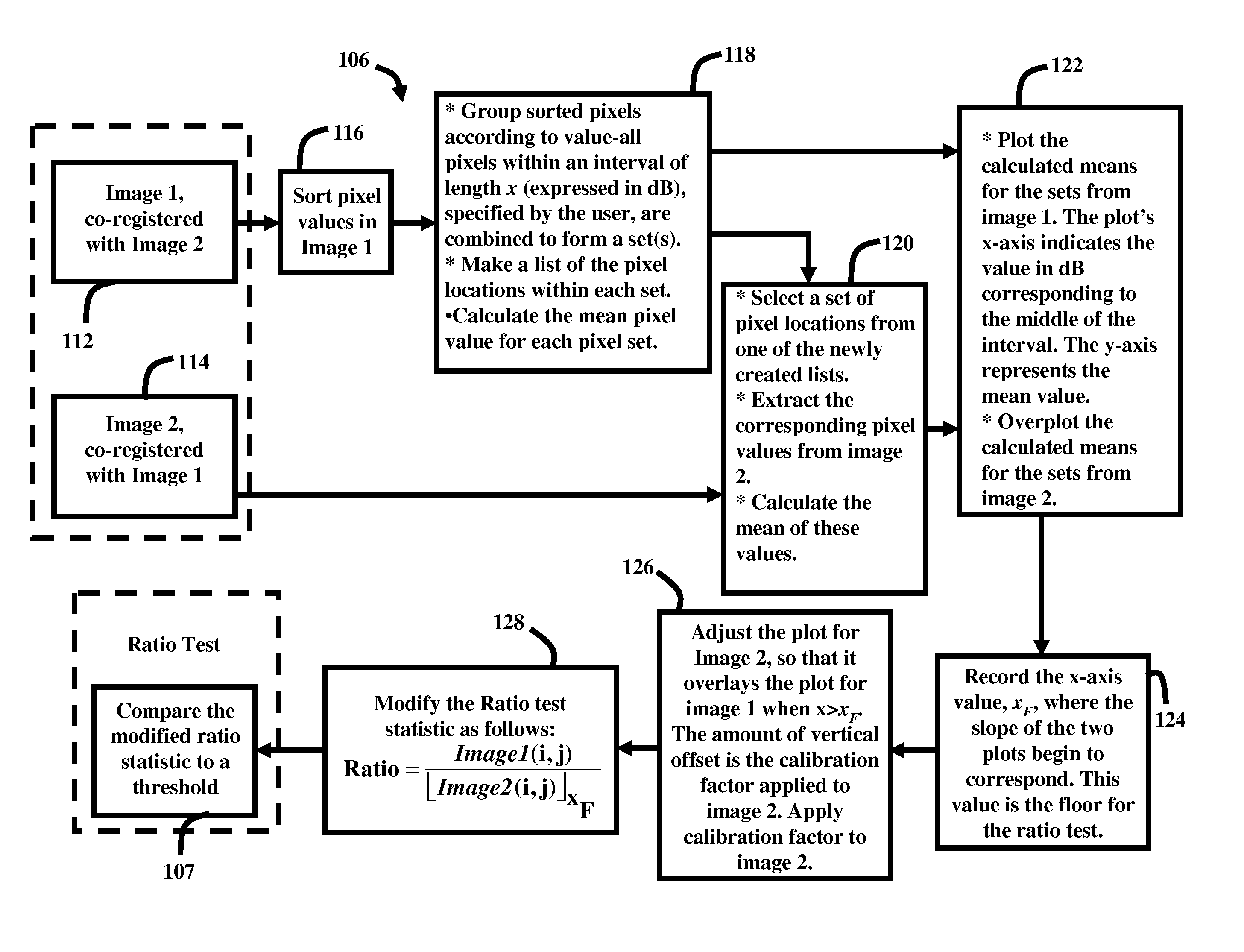
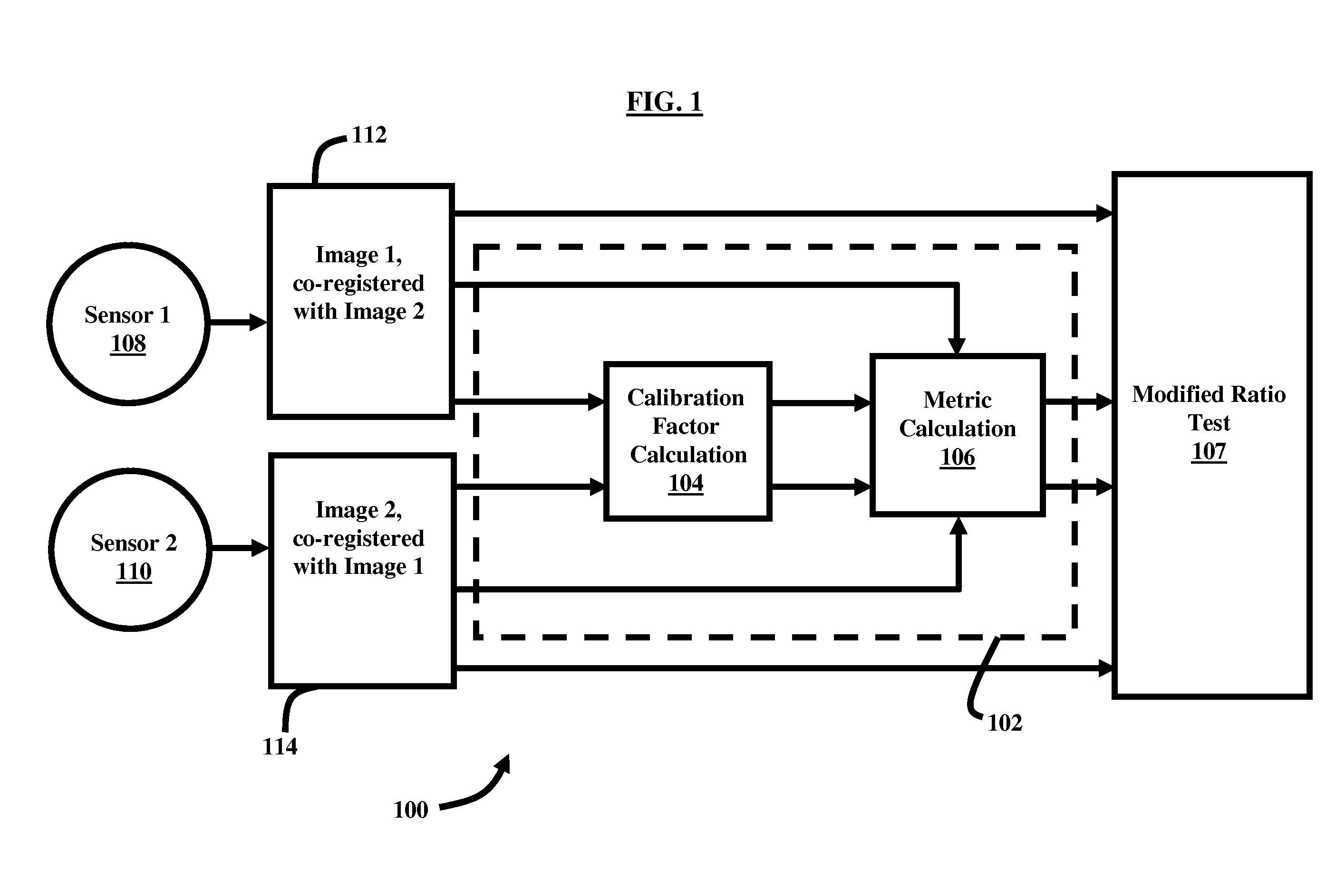
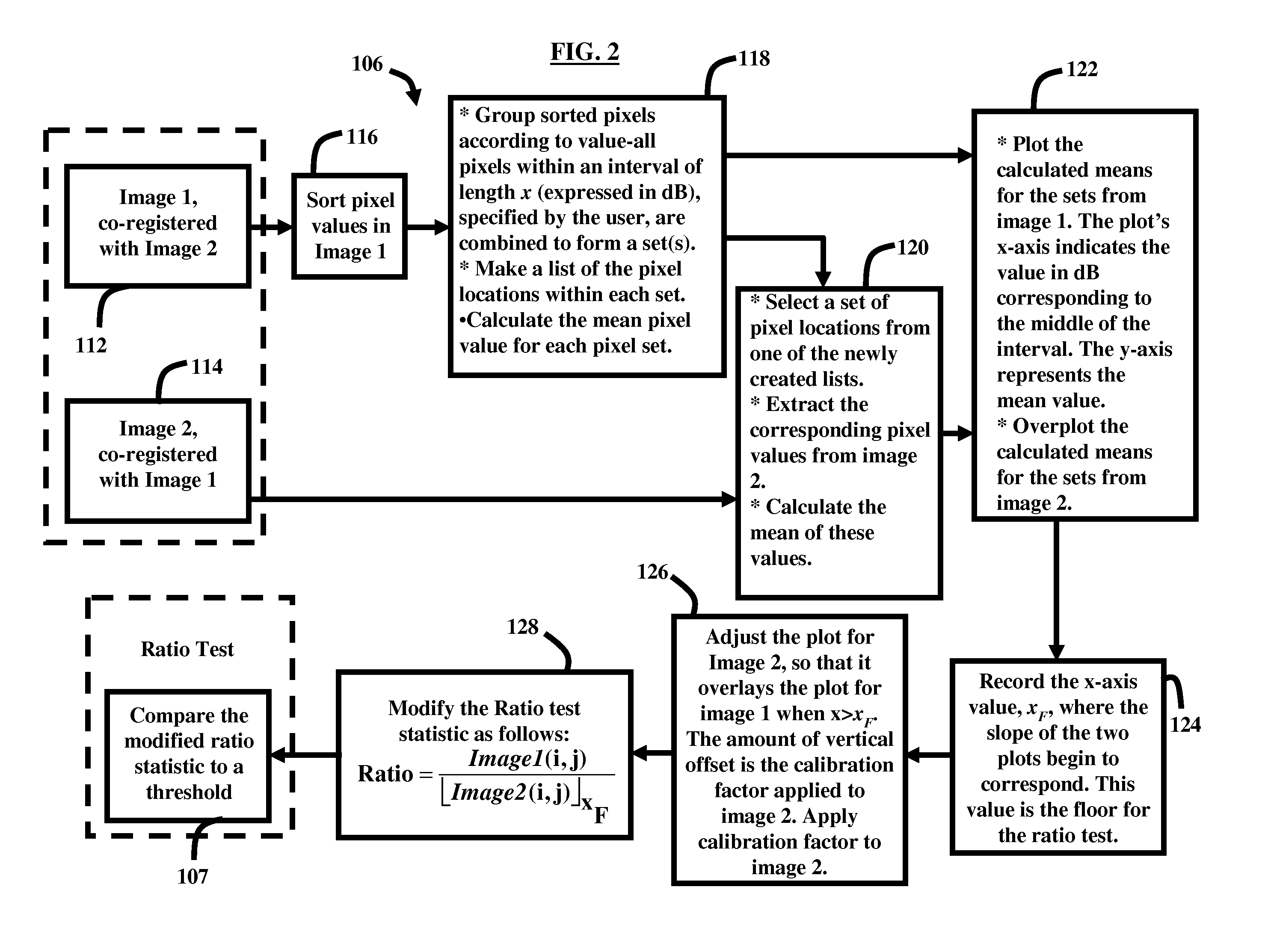
[0026]The embodiments herein provide a system and method for enhancing a ratio-based change in detection methodologies based on a SAR system's current noise and clutter background characteristics. The embodiments herein enhance the performance of the resulting, modified ratio-based change detec...


PUM


Abstract

Self-calibrating an automatic, surveillance-based change detection system operating on noisy imagery comprises detecting a first image co-registered with a second image, wherein the first image and the second image each comprise pixels of a noisy image of a scene; detecting the second image co-registered with the first image, wherein co-registration of the first image with the second image comprises pixels from different images corresponding to a same location within the scene; producing a calibration factor based on the co-registered images; producing a modified ratio of pixel values corresponding to the first image and the second image from the same location within the scene; and comparing the modified ratio to a pre-determined threshold ratio value.

Description

CROSS REFERENCE TO RELATED APPLICATIONS[0001]This patent application claims the benefit of U.S. Provisional Patent application No. 61 / 161,188 filed Mar. 18, 2009. U.S. Provisional Patent application No. 61 / 161,188 is hereby incorporated herein by reference in its entirety.GOVERNMENT INTEREST[0002]The invention described herein may be manufactured, used, and licensed by or for the United States Government.BACKGROUND[0003]1. Technical Field[0004]The embodiments herein generally relate to computerized image systems and, more particularly, to detection systems for comparing changes in imagery.[0005]2. Description of the Related Art[0006]The highly variable nature of radar measurements has plagued automatic target detection algorithm developers for decades. In particular, the variability introduced (in certain circumstances) by system noise and synthetic aperture processing compound the problem for small targets. While a change detection mode of operation may allow the detector to combat...

Claims


Application Information

Patent Timeline
Patent Type & Authority Patents(United States)
IPC IPC(8): G01S13/90G06K9/68H04N17/00G01S7/40
CPCG06K9/00711G06T7/002G06T2207/30232G06T7/85G06V20/40
Inventor RANNEY, KENNETH I.SICHINA, JEFFREY
Owner UNITED STATES OF AMERICA THE AS REPRESENTED BY THE SEC OF THE ARMY
Why Eureka
Try Eureka