Defogged image denoising method based on transmissivity

A transmittance and image technology, applied in image enhancement, image data processing, instruments, etc., can solve the problems of long running time, loss of details, and high computational cost of algorithms, achieve accurate similarity weight calculation, improve pixel reliability, The effect of reducing algorithm complexity

Active Publication Date: 2013-09-04
NAT UNIV OF DEFENSE TECH
View PDF1 Cites 28 Cited by
  • Summary
  • Abstract
  • Description
  • Claims
  • Application Information

AI Technical Summary

Problems solved by technology

[0012] 1. Denoising parameters need to be manually set;
[0013] 2. In step (2), it is necessary to operate on all pixels in the neighborhood of each to-be-denoised point, and the calculation cost of the algorithm is high and the running time is long;
[0014] 3. In step (3), the credibility and correctness of the given pixel similarity weights have not been considered;
[0015] 4. It does not take into account the characteristics that the dehazing image noise is mainly concentrated in bright areas such as the sky and dense fog, and the denoising results cannot maintain effective details
Some people also consider the interaction between the denoising strength, the noise variance and the comparison window, and model the weight attenuation coefficient h as h 2 =2β|N i |σ 2 , but still only determine the optimization parameters in the global sense of the image, and there are still varying degrees of local detail loss; someone else proposed a method for adaptively determining h based on the empirical standard deviation of the pixel block, although the edge is better protected fine detail, but falsely removes non-sequential, non-repeating patterns in the image
Others perform non-local average processing on the noisy image twice, and use the method noise calculated by the first processing result as a basis to correct and determine the similarity weight of pixels in the second processing, thereby improving the denoising effect, but must be at the expense of processing time

Method used


Image

  • Defogged image denoising method based on transmissivity
  • Defogged image denoising method based on transmissivity
  • Defogged image denoising method based on transmissivity

Examples


Embodiment Construction

[0047] The present invention will be further described in detail below in conjunction with the accompanying drawings and specific embodiments.

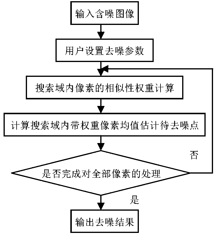
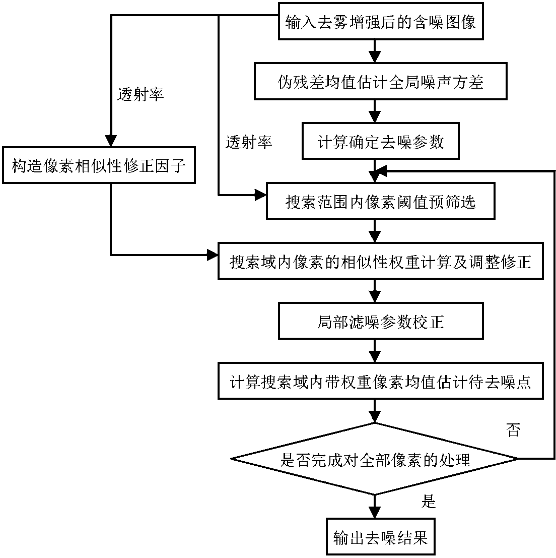
[0048] The transmissivity-based defogging image denoising method of the present invention is a non-local mean value denoising method based on transmissivity for pre-screening and weight correction. It first uses the transmittance obtained in the dark channel prior defogging process to complete the similarity pixel pre-screening, and constructs the pixel similarity weight correction factor; then according to the proposed parameter optimization model based on the difference between the global and local gradient mean values, it can be used for different regions. Adaptively determine the appropriate denoising parameters.

[0049] like figure 2 Shown, the detailed steps of the present invention are:

[0050] (1) Using the dark channel prior dehazing method to obtain the dehazed image with noise and its corresponding transmittance image;...


PUM


Abstract

A defogged image denoising method based on transmissivity comprises the steps: (1) obtaining a defogged image containing noise and a transmissivity image, (2) roughly estimating an overall noise variance, (3) according to the noise variance confirmed in the step (2), confirming and calculating several parameters, (4) according to the parameters, searching similar pixels, using the transmissivity as a criterion, pre-screening the pixels in the searching range, and removing points dissimilar to pixels to be denoised, (5) constructing a correction factor based on the transmissivity and weakening pixel weight polluted by the noise, (6) calculating a gradient mean value difference of a whole image and a searching window, inputting a built parameter optimization model, and conducting adaptive correction on denoising parameters in different areas, (7) calculating a similarity weighted mean value of all the pixels in the searching range to replace the pixels to be denoised, and (8) outputting a denoising result after all the pixels are processed. The defogged image denoising method has the advantages of being high in detail protection degree, good in denoising effect, low in complexity and the like.

Description

technical field [0001] The invention mainly relates to the technical field of image signal processing, in particular to a transmissivity-based dehazing image denoising method, which is applicable to non-local mean denoising, dark channel prior dehazing, parameter optimization modeling and the like. Background technique [0002] Under fog, haze and other weather conditions, the reflected light of objects in outdoor scenes is attenuated and scattered to varying degrees, resulting in serious quality degradation problems such as contrast drop and color shift in the collected images, which has become a threat to urban traffic, sea and air navigation safety. one of the main factors. [0003] Some practitioners proposed an image defogging algorithm based on dark channel prior, which significantly improves the visibility of images. However, the noise problem was not considered. Foggy images collected by low-cost cameras usually have a lot of noise, and the noise will be enhanced t...

Claims


Application Information

Patent Timeline
Patent Type & Authority Applications(China)
IPC IPC(8): G06T5/00
Inventor 刘肖琳曾宇骏
Owner NAT UNIV OF DEFENSE TECH
Why Eureka
Try Eureka