
Rotating irradiation therapy apparatus

a technology of irradiation therapy and rotating cylinder, which is applied in the field of rotating irradiation therapy apparatus, can solve the problems of obstructing the development and spread of cancer treatment based on particle beam, increasing the mass of the gantry cylinder, etc., and achieves the effect of high irradiation accuracy

Inactive Publication Date: 2011-06-14
HITACHI LTD
View PDF11 Cites 154 Cited by
  • Summary
  • Abstract
  • Description
  • Claims
  • Application Information

AI Technical Summary

Benefits of technology

The technical effect of this patent is to develop a small-size, lightweight rotating irradiation apparatus for particle beam therapy that can provide increased therapy accuracy and minimize the movement of the irradiation position due to the rotation of the gantry. This is important for ensuring the effectiveness of therapy and reducing the cost of the system introduction.

Problems solved by technology

However, an increase in the rigidity of the rotating gantry increases the mass of the gantry cylinder.
An increase in the mass of the rotating gantry increases the cost of particle beam therapy system introduction (e.g., the cost of particle beam therapy facility construction, the cost of apparatus transportation to a facility, and the cost of apparatus installation), thereby obstructing the development and spread of cancer treatment based on a particle beam.

Method used


Image

  • Rotating irradiation therapy apparatus
  • Rotating irradiation therapy apparatus
  • Rotating irradiation therapy apparatus

Examples


first embodiment

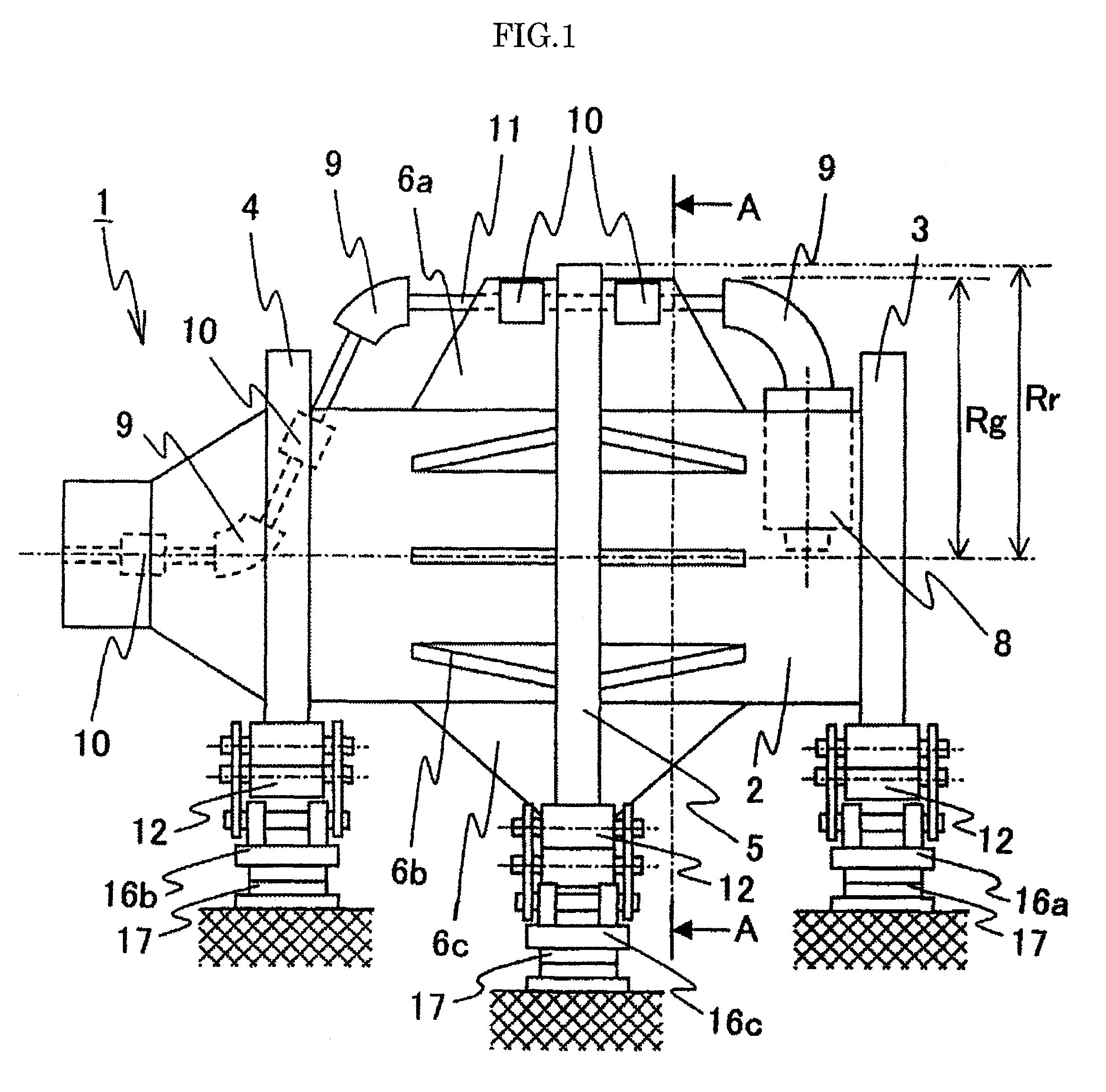
[0029]First of all, a first configuration example of a rotating irradiation apparatus according to the first embodiment will be described with reference to FIGS. 1 to 5.

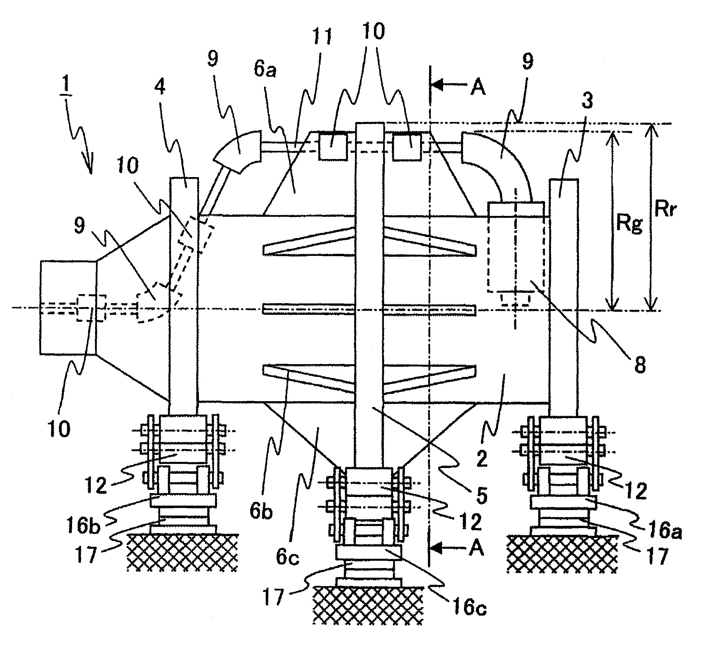
[0030]FIG. 1 is a side view illustrating the overall configuration of the rotating irradiation apparatus.

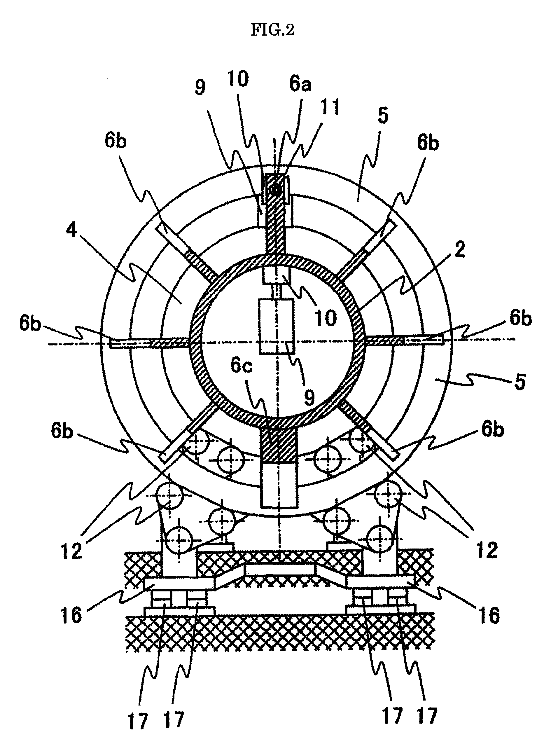
[0031]FIG. 2 is a rear view that is taken from cross-section line A-A in FIG. 1 to show the left side of FIG. 1.

[0032]FIG. 3 is a schematic diagram illustrating a beam transport system and a beam irradiation device, which are positioned in the rotating irradiation apparatus.

[0033]FIG. 4 is a side view obtained when a rotating section of the rotating irradiation apparatus is rotated from the position indicated in FIG. 1 by 180 degrees about a rotation axis.

[0034]FIG. 5 is a rear view that is taken from cross-section line A-A in FIG. 4 to show the left side of FIG. 4.

[0035]It should be noted that FIGS. 4 and 5 show only rollers 12 as component parts of a rotating body support device 16.

[0036]Referring to FIGS. 1 and...

second embodiment

[0059]A configuration example of the rotating irradiation apparatus according to a second embodiment of the present invention will now be described with reference to FIGS. 14 and 15.

[0060]FIG. 14 is a side view illustrating a configuration example of the rotating irradiation apparatus according to the second embodiment of the present invention.

[0061]FIG. 15 is a rear view that is taken from cross-section line A-A in FIG. 14 to show the left side of FIG. 14.

[0062]As is the case with the configuration examples of the first embodiment, the rotating irradiation apparatus shown in FIGS. 14 and 15 is such that the intermediate ring connection member 6c not only serves to fix the intermediate ring 5 to the gantry cylinder 2 but also functions as a counterbalance weight. Further, the intermediate ring connection member 6a serves not only to fix the intermediate ring 5 to the gantry cylinder 2 but also to fix the beam transport devices 10 and vacuum duct 11 to the gantry cylinder.

[0063]Howev...


PUM


Abstract

A rotating irradiation therapy apparatus used for particle beam therapy includes a rotating gantry equipped with a charged particle beam irradiation device beam transport devices for guiding a charged particle beam to the irradiation device and a roller in contact with a ring member included in the rotating gantry and supporting the gantry. A front ring is disposed in contact with the roller of a rotating body support device at one end in the axial direction of the rotating gantry, and a rear ring is disposed in contact with the roller at the other end in the axial direction of the rotating gantry. At least one intermediate ring is disposed in a position different in the axial direction of the gantry between the front and rear rings and in contact with the roller.

Description

TECHNICAL FIELD[0001]The present invention relates to a rotating irradiation therapy apparatus that irradiates an affected part of a body with an ion beam.BACKGROUND ART[0002]An ion beam irradiation system, which is a rotating irradiation therapy apparatus, treats cancer by irradiating an affected part of a patient's body with a proton beam, carbon ion beam, or other ion beam.[0003]The ion beam irradiation system includes a rotating gantry, which is a rotating irradiation therapy apparatus. As disclosed, for instance, in Patent Document 1, the rotating gantry includes a front ring, a rear ring, and a gantry cylinder for connecting the front and rear rings. A beam transport device (beam path), which guides an ion beam, and an irradiation device (irradiation nozzle) are mounted on the gantry cylinder.[0004]The mass of a beam transport system, which includes the aforementioned beam transport device and irradiation device, is used to generate a moment about a rotation axis of the rotati...

Claims


Application Information

Patent Timeline
Patent Type & Authority Patents(United States)
IPC IPC(8): A61N5/10A61N5/00
CPCA61N5/10G21K5/10A61N5/1081A61N2005/1087
Inventor TAKEDA, NORIOKANEKO, SHIGEJIYAMASHITA, TSUTOMUSAGA, HIROSHI
Owner HITACHI LTD
Learn More