Cylinder device

a cylinder and piston technology, applied in the direction of rotary clutches, braking systems, fluid couplings, etc., can solve the problems of cup seal collapse, ineffective stroke of pistons are varied, ineffective stroke of pistons are increased, etc., to prevent the ineffective stroke of pistons from increasing or varying, and secure proper seal performance. , the effect of simple structur

Active Publication Date: 2011-06-21
HITACHI ASTEMO LTD
View PDF6 Cites 5 Cited by
  • Summary
  • Abstract
  • Description
  • Claims
  • Application Information

AI Technical Summary

Benefits of technology

[0008]In solving the above problems found in the conventional cylinder device, it is an object of the invention to provide a cylinder device which, by using a simple structure, can restrict the movement of the cup seal in the cylinder axial direction to thereby prevent the ineffective stroke of the piston from increasing or varying and also can secure proper seal performance between the inner circumferential lip and piston.
[0027]According to a cylinder device of the invention, since the length from the leading end portions of the elastic projections to the base end face of the base portion is set longer than axial length of the seal groove, the movement of the cup seal in the cylinder axial direction is restricted to thereby prevent the ineffective stroke from increasing or varying. Further, since, due to the contact between the elastic projections and the cylinder hole bottom portion side surface of the seal groove, a force is imparted on the inner circumferential lip toward the cylinder hole inner circumferential direction, it is possible to secure a good sealing property between the inner circumferential lip and piston.
[0028]Further, when the leading ends of the elastic projections provided on the cup seal are contacted with the cylinder hole bottom portion side surface of the seal groove in a state where the leading ends are flexed toward the piston, due to a reactive force caused by flex of the leading ends, the inner circumferential lip of the cup seal can be urged toward the piston more positively.
[0029]Furthermore, when the cylinder hole bottom portion side surface of the seal groove is formed in a conical surface shape in which axial length from the cylinder hole opening side surface increases gradually toward the inner circumferential side, in a reactive force caused by the contact between the elastic projections and the cylinder hole bottom portion side surface of the seal groove, a component acting in the cylinder hole inner circumferential direction can be increased. Thus, the inner circumferential lip of the cup seal can be urged toward the piston side more positively. Also, the efficiency of the assembling operation of the cup seal into the seal groove can be enhanced and the leading end sides of the elastic projections can be flexed in the piston direction easily.
[0030]When a plurality of reinforcing portions are formed in the outer circumferential surface of the inner circumferential lip and elastic projections are provided on the leading ends of these reinforcing portions, rigidity of the inner circumferential lip can be enhanced and a stable sealing property can be secured. When compared with a structure in which the elastic projections are projected from the outer circumference of the leading end of the inner circumferential lip, a space in which the elastic projections can be flexed in the piston direction can be increased.

Problems solved by technology

In the conventional cylinder device disclosed in the above-mentioned the JP-A-2004-231093, however, since the cup seal is fitted into the seal groove with a clearance in the axial direction of the cylinder, when the piston is operated, the cup seal can be moved in the cylinder axial direction, thereby raising a fear that the ineffective stroke of the piston is increased or the ineffective stroke of the piston is varied.
Further, in the conventional hydraulic master cylinder of the plunger type disclosed in the JP-A-2005-186925, although the projection is provided on the cup seal to prevent the cup seal from moving in the cylinder axial direction, the cup seal is caused to collapse when the piston is returned quickly.

Method used


Image

  • Cylinder device
  • Cylinder device
  • Cylinder device

Examples


Embodiment Construction

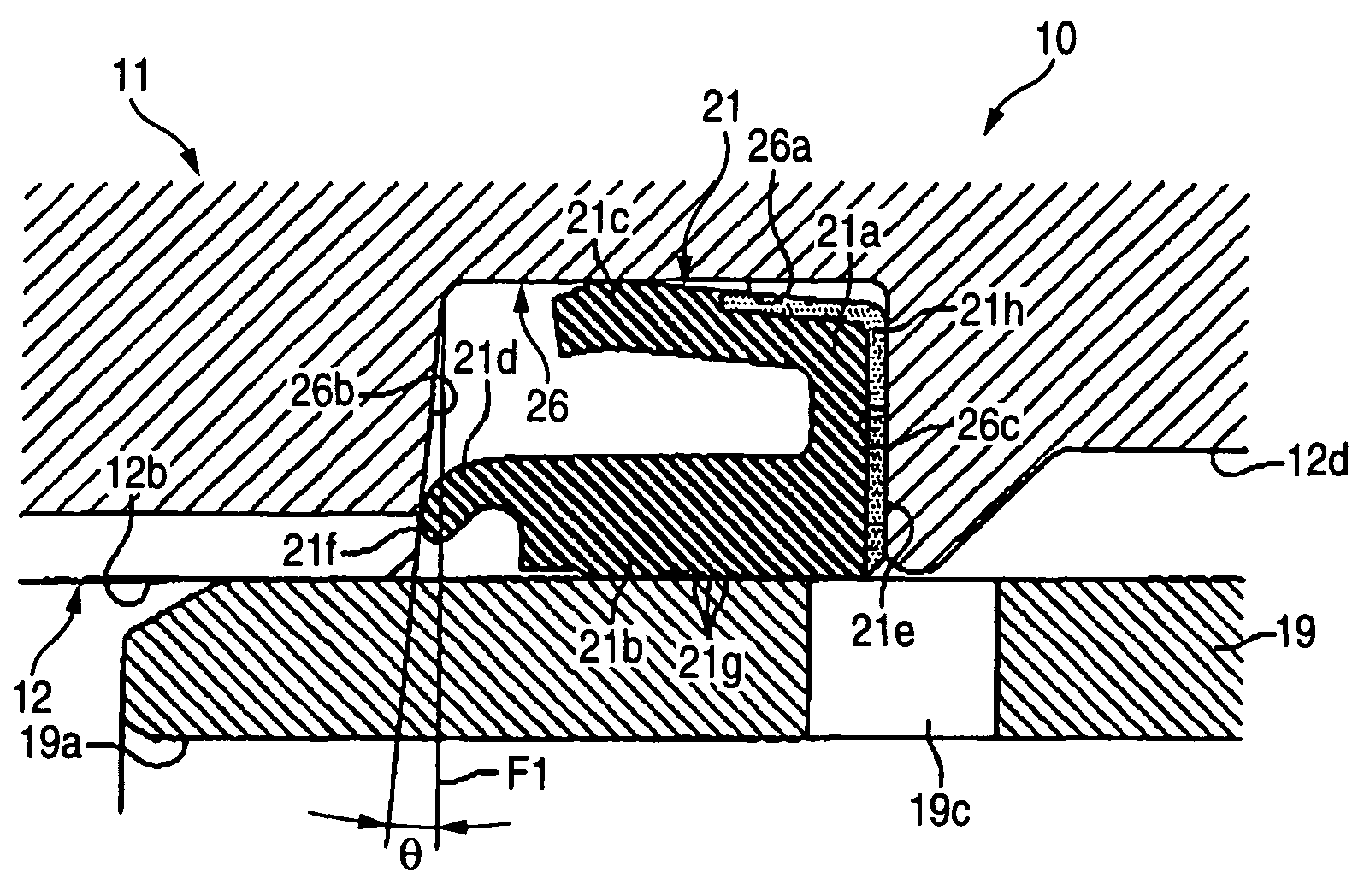
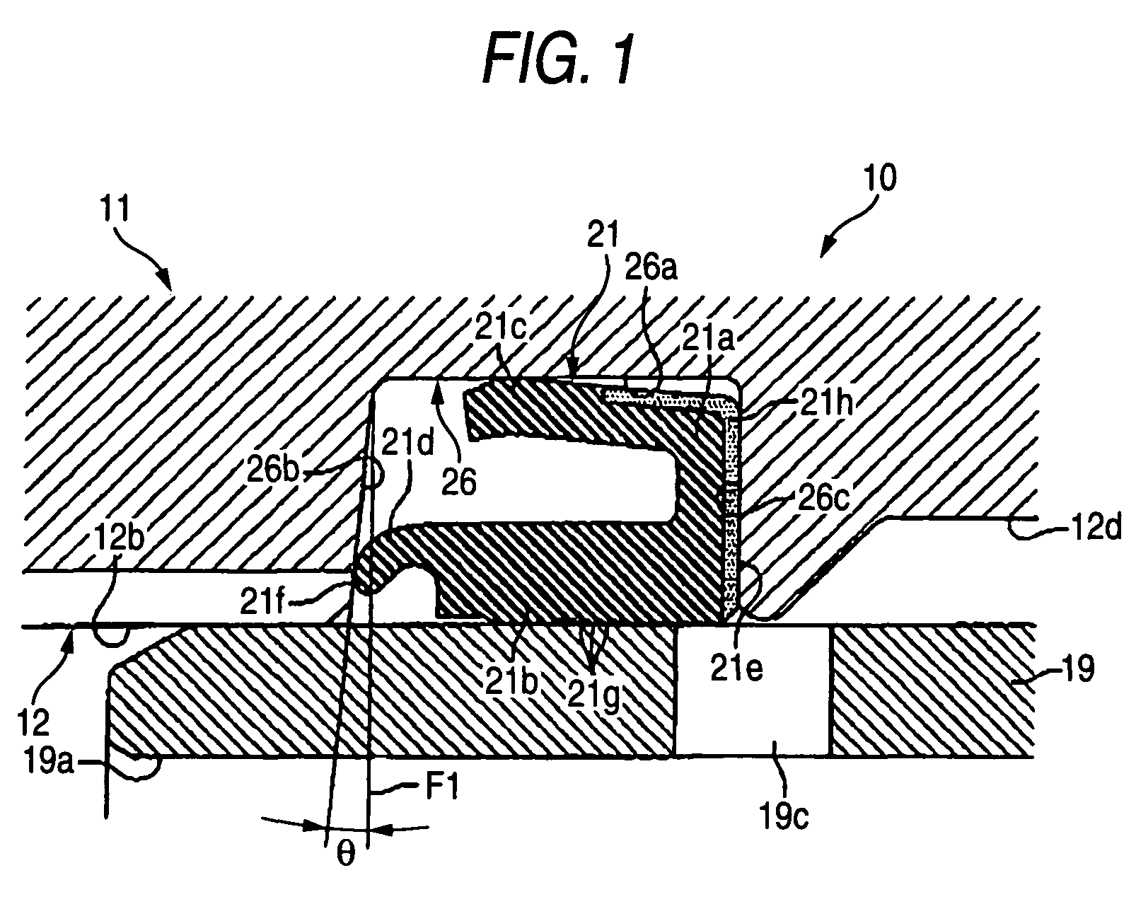
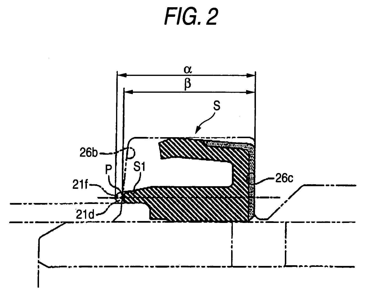
[0037]Hereinafter, description will be given below in detail of embodiments in which the invention is applied to a hydraulic master cylinder of plunger type for a vehicle with reference to the accompanying drawings. FIGS. 1 to 4 show a first embodiment according to the invention. Specifically, FIG. 1 is an enlarged section view of the main portions of a hydraulic master cylinder, FIG. 2 is an explanatory view of the length of a cup seal in the cylinder axial direction, FIG. 3 is a section view of the hydraulic master cylinder and FIG. 4 is a partially cut-out perspective view of the cup seal.

[0038]The hydraulic master cylinder 10 includes a cylinder main body 11. The cylinder main body 11 includes a bottomed cylinder hole 12, a first output port 13 opened up in the cylinder axial direction intermediate portion of the cylinder hole 12 and a second output port 14 opened up on the bottom portion side of the cylinder hole 12.

[0039]The cylinder main body 11 further includes a pair of bos...


PUM


Abstract

A cup seal 21 includes a base portion 21a, an inner circumferential lip 21b slidingly contactable with a plunger 19 and an outer circumferential lip 21c contactable with the bottom surface 26a of the seal groove 26. Further, on the cup seal 21, there are provided elastic projections 21d projecting from the outer circumferential side leading end of the inner circumferential lip 21b toward the cylinder hole bottom portion. The length of the cup seal 21 from the base end face 21e to the leading end portions 21f is set longer than axial length of the seal groove 26. When the cup seal 21 is fitted into the seal groove 26, force is imparted on the inner circumferential lip 21b toward the cylinder hole inner circumferential direction to energize the inner circumferential lip 21b toward the piston all the time.

Description

BACKGROUND OF THE INVENTION[0001]1. Field of the Invention[0002]The present invention relates to a cylinder device and, specifically, it relates to a cylinder device structured such that a piston is movably inserted into a cylinder through a cup seal, for example, a hydraulic master cylinder of a plunger type for a vehicle.[0003]2. Description of Related Art[0004]Conventionally, there is known a cylinder device structured such that, a annular seal groove is formed on an inner circumferential surface of a cylinder within which a piston is inserted and a cup seal is fitted into the seal groove. Herein, the cup includes a base portion to be fitted with the cylinder hole opening side surface of the seal groove, an inner circumferential lip extending from the inner circumferential side of the base portion of the cup seal to the bottom portion side of the cylinder hole of the cylinder and an outer circumferential lip extending from the outer circumferential side of the base portion of the...

Claims


Application Information

Patent Timeline
Patent Type & Authority Patents(United States)
IPC IPC(8): F16J15/32F15B7/08B60T11/16B60T11/228F16J15/18F16J15/3236
CPCF15B7/08F16J15/3236F16J15/166F16D2025/081
Inventor HANAOKA, MITSUHIROUENO, OSAMUMITANI, TOSHIAKISHINOHARA, TAKAYOSHI
Owner HITACHI ASTEMO LTD
Why Eureka
Try Eureka