Working machine

a technology of working machine and working mode, which is applied in the direction of lifting device, crane, vehicle spring, etc., can solve the problems of disconcerting machine operator between one operating mode and another, and achieve the effect of maximum stability

Active Publication Date: 2011-06-21
J C BAMFORD EXCAVATORS LTD
View PDF21 Cites 7 Cited by
  • Summary
  • Abstract
  • Description
  • Claims
  • Application Information

AI Technical Summary

Benefits of technology

[0009]Desirably, when the machine is stationary, the controller operates the control valve to prevent fluid flow in the hydraulic system so as to prevent axle movement relative to the body, and the controller operates the control valve to permit more fluid flow as the machine speed increases, at least to the threshold speed at which the control valve may provide substantially no restriction to fluid flow so that the axle may freely move as permitted by its mounting.
[0015]The invention has particularly but non-exclusively been developed for a working machine of the kind which includes a loading arm which is pivoted to the body for up and down movement relative to the machine, e.g. at a rear of the body, the loading arm extending beyond a front end of the body and mounting a load handling implement. The loading arm may be telescopically extendible and retractable. The stability of such a machine, particularly when handling loads at great height above and distant from the body of the machine is crucial. The present invention, in which the control valve is operable to prevent or at least maximally restrict fluid flow and hence axle movement, provides for maximum stability during load handling. The control actuator is preferably provided between a rear axle and the body, and the axle with the sway actuator, where provided, is the front axle.

Problems solved by technology

Such automatic switching between one operating mode and another can be disconcerting for a machine operator.

Method used


Image

  • Working machine
  • Working machine
  • Working machine

Examples


Embodiment Construction

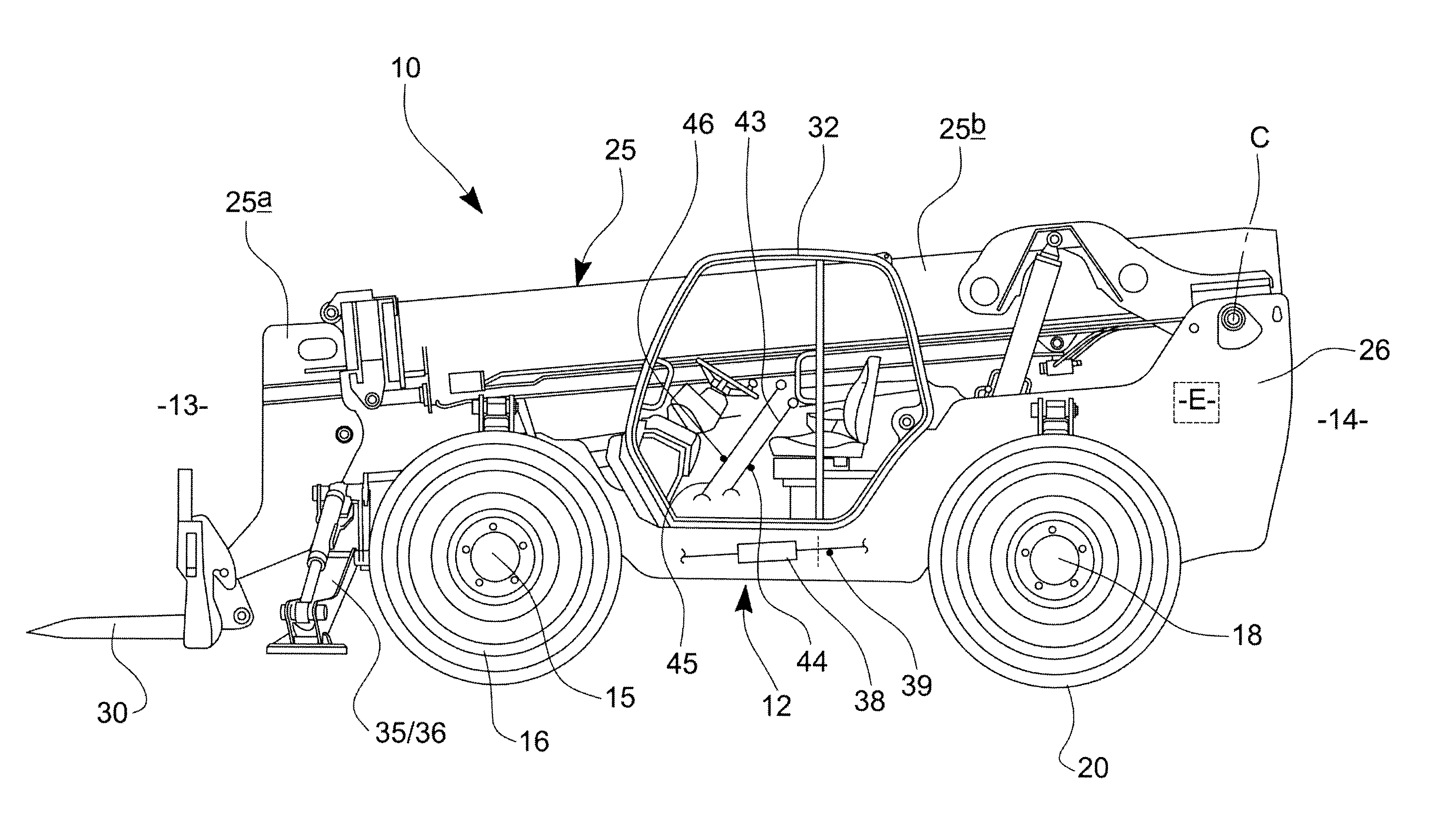
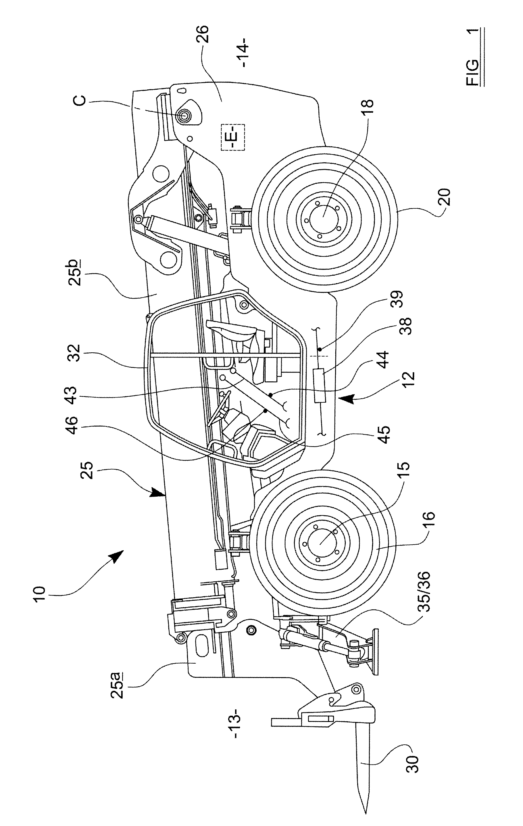
[0030]Referring to the drawings a working machine 10 in this example is a load handling machine, which includes a body 12 having a front end 13 and a rear end 14. Towards a front end of the machine 10 there is a front axle 15 which carries at or near to each end, a front wheel 16, and towards the rear end 14, there is a rear axle 18 which carries at or near each end, a rear wheel 20.

[0031]Each of the front 15 and rear 18 axles in this example are pivotally mounted with respect to the body 12 about respective pivot axes A, B. The pivot axes A, B are generally horizontal and extend longitudinally of the machine 10, and in this example are substantially co-axial.

[0032]The machine 10 further mounts a loading arm 25 for pivoting up and down movement about a further generally horizontal axis C which is transverse to the pivot axes A, B of the axles 15, 18. The loading arm 25 is mounted on a mounting structure 26 at or toward the rear end 14 of the body 12 and extends forwardly beyond the ...


PUM


Abstract

A working machine includes a body and an axle which is mounted so as to be moveable relative to the body, the axle carrying at or towards each end, a ground engaging wheel by means of which the machine can travel over the ground, the machine including a speed sensor sensitive to the machine ground speed, and there being a hydraulic control system including at least one control actuator connected between the body and the axle for controlling movement of the axle relative to the body, and the hydraulic system further including at least one control valve which is operable to restrict fluid flow occurring as a result of the control actuator extending or retracting in response to axle movements relative to the body, depending upon the signal provided by the speed sensor, wherein the control valve is an electrically operated control valve, operated proportionally by a valve controller which responds to changes in machine speed, by adjusting the restriction to fluid flow so as to permit more fluid flow as the machine speed increases.

Description

BACKGROUND TO THE INVENTION[0001]This invention relates to a working machine which includes an axle carrying ground engaging wheels, which is moveable relative to a body of the machine.[0002]More particularly but not exclusively the invention relates to a working machine of the kind which has a working arm which is moveable relative to the body of the machine, the working arm carrying a working implement such as a loading forks or loading or excavating bucket for examples only.[0003]However the invention may be applied to other working machines such as tractors. The axle may be suspended from the body, or may be fixed to pivot about a pivot axis relative to the body.[0004]Such working machines are required to be driven over ground which typically will include many surface irregularities. To facilitate machine travel it is well known to mount one of the axles for pivoting movement relative to the body, about a generally horizontal axis which extends longitudinally of the machine. Suc...

Claims


Application Information

Patent Timeline
Patent Type & Authority Patents(United States)
IPC IPC(8): B60G17/02
CPCB60G9/02B60G17/005B66F9/22B66F9/0655B60G2200/322B60G2202/413B60G2300/06B60G2400/204B60G2204/4605B60G17/01933B60G17/056
Inventor NORTH, ALEXANDERFORD, KEVIN W.
Owner J C BAMFORD EXCAVATORS LTD
Why Eureka
Try Eureka