
Bipolar electrosurgical instrument for sealing vessels

a technology of electrosurgical instruments and blood vessels, applied in the field of electrosurgical instruments, can solve the problems of inability to apply the correct pressure to the blood vessel, the instrument is not designed to seal the blood vessel with a diameter larger than about two millimeters, and the simplicity and familiarity of the instrument are not combined, so as to improve the efficiency of the surgical procedure, reduce the time of operation, and improve the access to target tissues

Inactive Publication Date: 2011-06-21
COVIDIEN AG
View PDF1041 Cites 64 Cited by
  • Summary
  • Abstract
  • Description
  • Claims
  • Application Information

AI Technical Summary

Benefits of technology

[0030]One advantage of the invention is that blood vessels can be quickly fused and permanently sealed against passage of blood or other fluids. The instrument thereby reduces operating-room time, provides improved access to target tissues, and increases the efficiency of the surgical procedure.
[0031]Another advantage is that no sutures or staples are required to permanently seal blood vessels, and no foreign material is left in the body of the patient.
[0032]Yet another advantage is that vessels can be sealed as the instrument is applied, and then the instrument can be removed from the surgical field. This keeps the surgical field clear of extraneous tools that may hinder the surgeon's access to the surgical site.
[0033]Yet another advantage is that the proper amount of pressure can be applied by the instrument to the vessel or vessels, thereby increasing the likelihood of a successful surgical outcome.
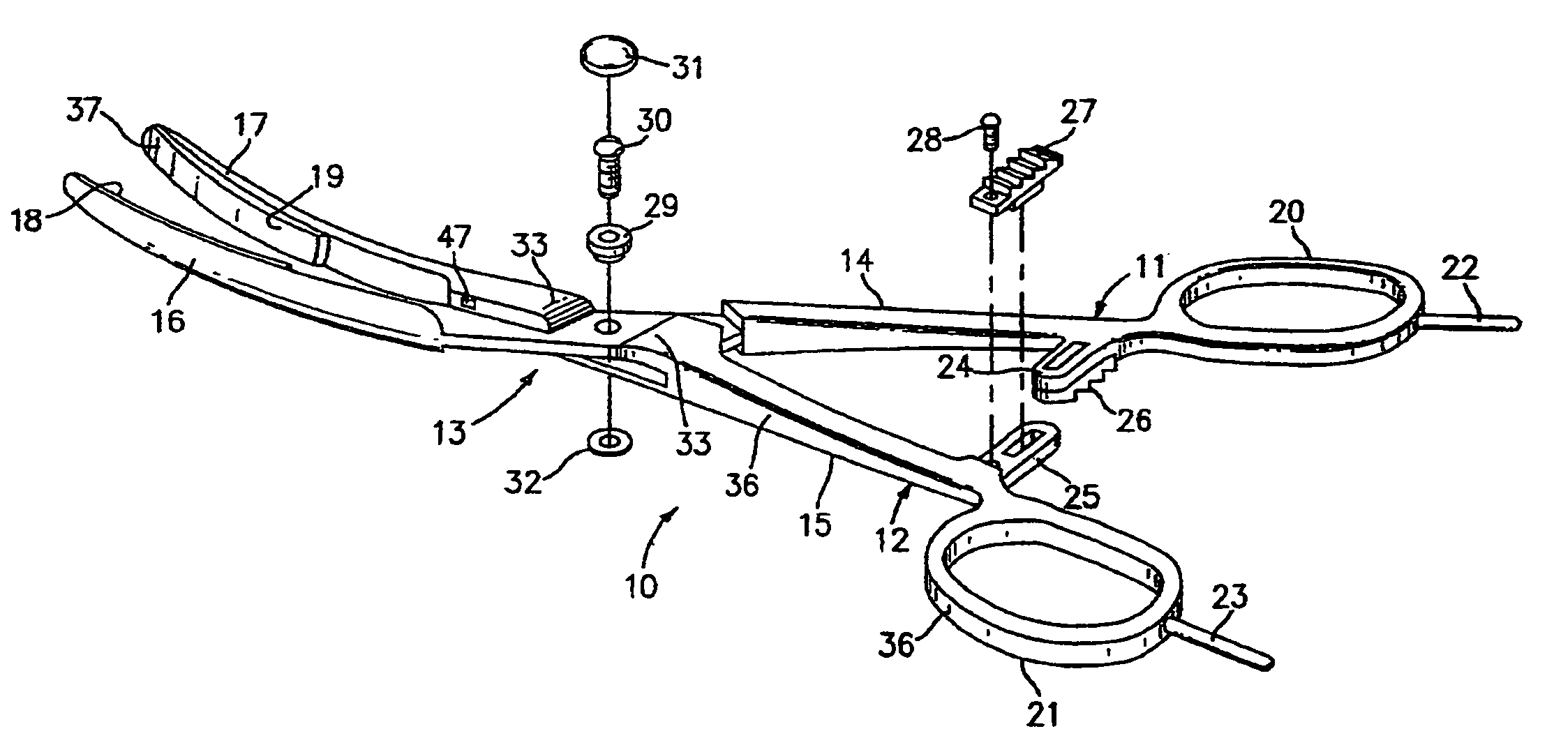
[0034]The bipolar electrosurgical instrument of the present invention comprises inner and outer members connected by an open lockbox, interlocking ratchet teeth, and electrical terminals with conductive pathways leading to seal surfaces. The inner and outer members each have a ring handle near a proximal end and an opposable seal surface near a distal end. The proximal end is held and controlled by the surgeon, while the distal end is used to manipulate tissue. The open lockbox joins the inner and outer members to allow arcuate motion of each opposable seal surface. The open lockbox is generally designed to provide lateral support so that both seal surfaces move in approximately the same plane. The seal surfaces are preferably aligned opposite each other when the instrument jaws are closed together. To provide lateral support, the open lockbox comprises a pivot and at least one flange extending over the inner member and attached to the outer member.
[0035]The instrument is tuned to provide a proper closure force by adjusting the dimensions of a shank portion on each of the inner and outer members. The shank portion is defined as the portion of each member bounded by its respective ratchet stub and the open lockbox. During use, the surgeon squeezes the ring handles to compress tissue between the seal surfaces. The shank portion of each member flexes in the manner of a cantilever spring, and can be locked in a deflected position with the ratchet to hold a constant force. It is one of the objects of the invention to provide a range of ratchet stops that correspond to a range of appropriate closure forces on the seal surfaces of the instrument.

Problems solved by technology

However, it has been found that these instruments are not capable of sealing blood vessels with diameters larger than about two millimeters.
However, these instruments are not designed to apply the correct pressure to a blood vessel to achieve a lasting seal.
All of these instruments also suffer from the drawback that they do not combine the simplicity and familiarity of a hemostat with a bipolar electrosurgical circuit.
Prior disclosures have not provided a design for a bipolar electrosurgical instrument capable of conveniently applying a constant pressure, from a calibrated spring-loaded source held by a ratchet, that is sufficient to seal vessels and vascular tissue.

Method used


Image

  • Bipolar electrosurgical instrument for sealing vessels
  • Bipolar electrosurgical instrument for sealing vessels
  • Bipolar electrosurgical instrument for sealing vessels

Examples


Embodiment Construction

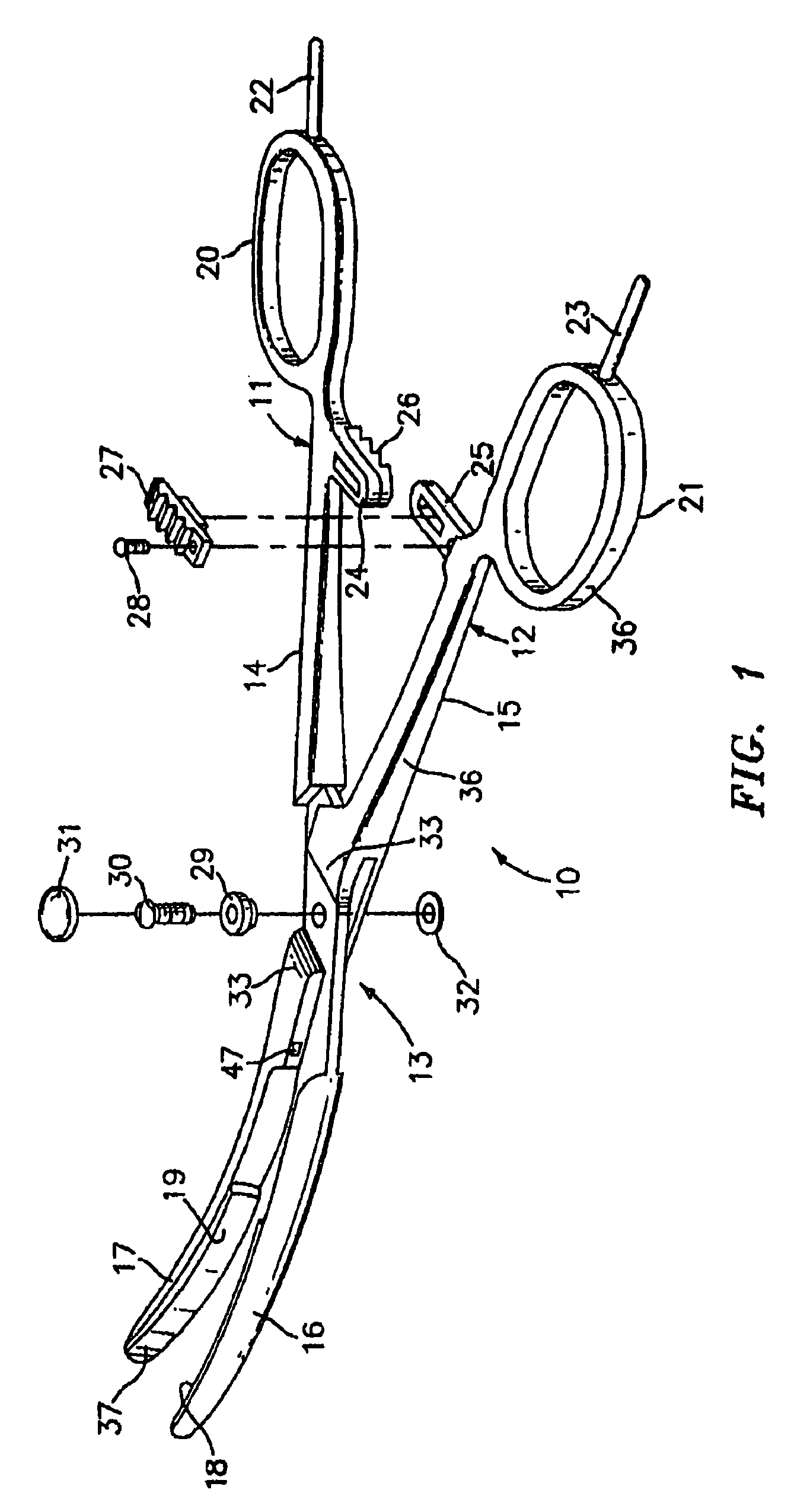
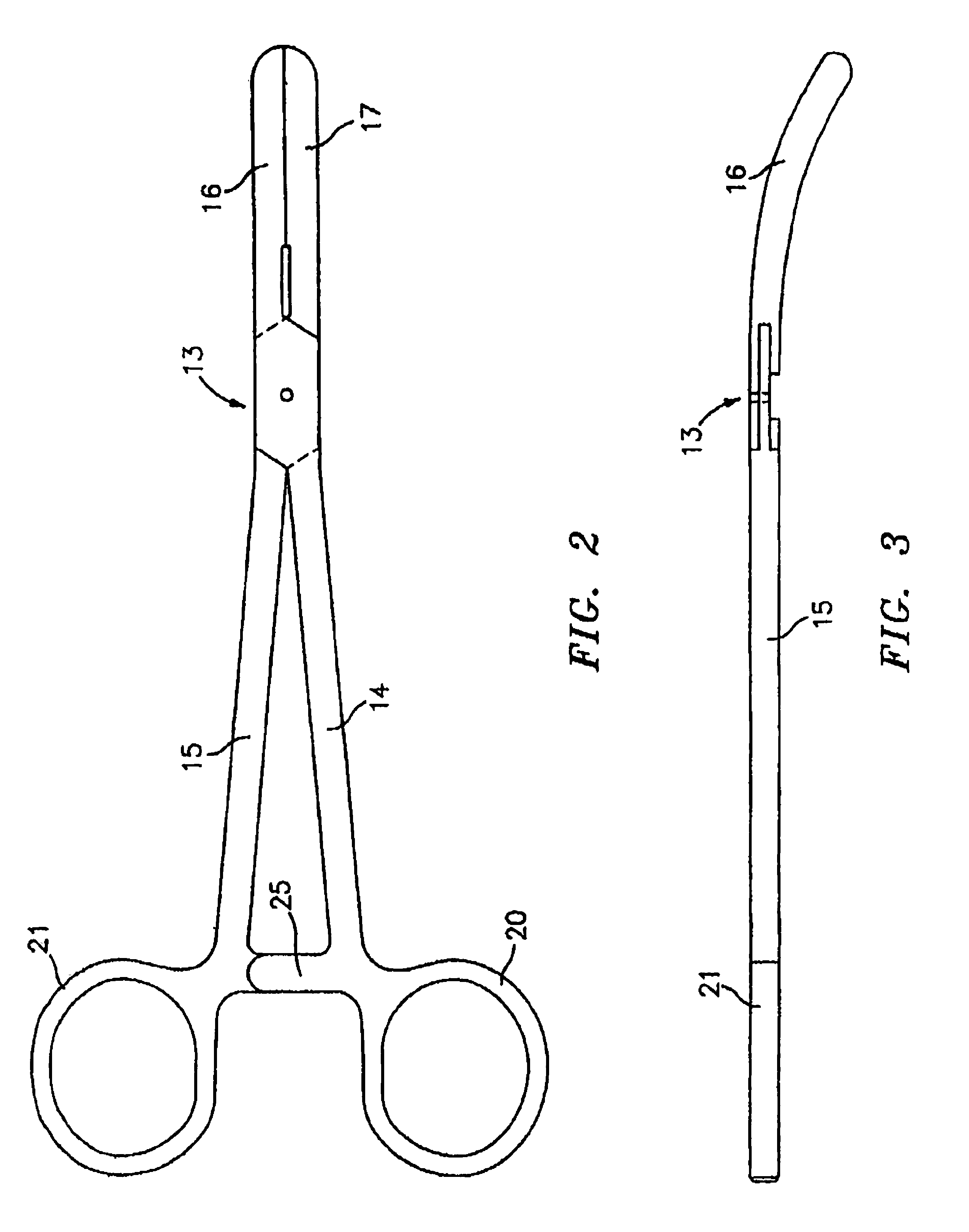
[0052]Referring to FIG. 1, the instrument 10 has an inner member 11 and an outer member 12. The members 11 and 12 are connected through an open lockbox 13 which has a gap between flanges 33. The terms “inner” and “outer” are used to distinguish the members 11 and 12, and their component parts, according to the members' respective positions at the open lockbox 13. The inner member 11 is fitted generally within the inner surfaces of the open lockbox 13 and is captured by the flanges 33. The outer member generally forms the outside surfaces of the open lockbox 13.

[0053]The inner member 11 has an inner shank 14, an inner jaw 16, and an inner ring handle 20. Similarly, the outer member 12 has an outer shank 15, an outer jaw 17, and an outer ring handle 21. The ring handles, 20 and 21, are designed for a surgeon to hold and manipulate the instrument 10. The jaws, 16 and 17, are designed to grasp tissue between the opposing seal surfaces 18 and 19.

[0054]Each shank, 14 and 15, has a respect...


PUM


Abstract

A bipolar electrosurgical instrument has opposable seal surfaces on its jaws for grasping and sealing vessels and vascular tissue. Inner and outer instrument members allow arcuate motion of the seal surfaces. An open lockbox provides a pivot with lateral support to maintain alignment of the lateral surfaces. Ratchets on the instrument members hold a constant closure force on the tissue during the seal process. A shank portion on each member is tuned to provide an appropriate spring force to hold the seal surfaces together. During surgery, the instrument can be used to grasp and clamp vascular tissue and apply bipolar electrosurgical current through the clamped tissue. In one embodiment, the seal surfaces are partially insulated to prevent a short circuit when the instrument jaws are closed together. In another embodiment, the seal surfaces are removably mounted on the jaws.

Description

CROSS REFERENCE TO RELATED APPLICATIONS[0001]This application is a continuation of U.S. application Ser. No. 10 / 736,180 filed on[0002]Dec. 15, 2003 by Buysse et al. entitled “BIPOLAR ELECTROSURGICAL INSTRUMENT FOR SEALING VESSELS” now U.S. Pat No. 7,241,296 which is a continuation of U.S. application Ser. No. 10 / 113,745 filed on Apr. 1, 2002 by Buysse et al. entitled “BIPOLAR ELECTROSURGICAL INSTRUMENT FOR SEALING VESSELS”, now U.S. Pat. No. 6,726,686, which is a continuation-in-part of U.S. application Ser. No. 10 / 090,081 filed on Mar. 1, 2002 by Buysse et al. entitled “BIPOLAR ELECTROSURGICAL INSTRUMENT FOR SEALING VESSELS”, now U.S. Pat. No. 6,743,229, which is a continuation of U.S. application Ser. No. 09 / 502,933 filed on Feb. 11, 2000 by Buysse et al. entitled “BIPOLAR ELECTROSURGICAL INSTRUMENT FOR SEALING VESSELS”, now U.S. Pat. No. 6,352,536, which is a continuation of U.S. application Ser. No. 08 / 968,779 filed on Nov. 12, 1997 by Buysse et al. entitled “BIPOLAR ELECTROSURG...

Claims


Application Information

Patent Timeline
Patent Type & Authority Patents(United States)
IPC IPC(8): A61B18/12A61B18/14
CPCA61B18/1442A61B2017/2945A61B2018/1432A61B2018/0063A61B2018/00083
Inventor BUYSSE, STEVEN P.SCHMALTZ, DALE F.COUTURE, GARY M.NGUYEN, LAP P.JOHNSON, KRISTIN D.
Owner COVIDIEN AG
Learn More