Method and system for controlling power to an electrically powered device

a technology of electrical power and power supply, applied in the integration of power network operation systems, coupling device connections, instruments, etc., can solve the problems of failure to disclose a system and method for remote control power, and achieve the effect of improving power saving efficiency, controlling and customization, and being effective in reducing power consumption

Active Publication Date: 2011-06-21
BEST ENERGY REDUCTION TECH
View PDF10 Cites 143 Cited by
  • Summary
  • Abstract
  • Description
  • Claims
  • Application Information

AI Technical Summary

Benefits of technology

[0013]The present invention provides a system and method for controlling power to an electrically powered device in a novel and efficient manne

Problems solved by technology

The prior art fails to disclose a system and method for remotely controllin

Method used


Image

  • Method and system for controlling power to an electrically powered device
  • Method and system for controlling power to an electrically powered device
  • Method and system for controlling power to an electrically powered device

Examples


Embodiment Construction

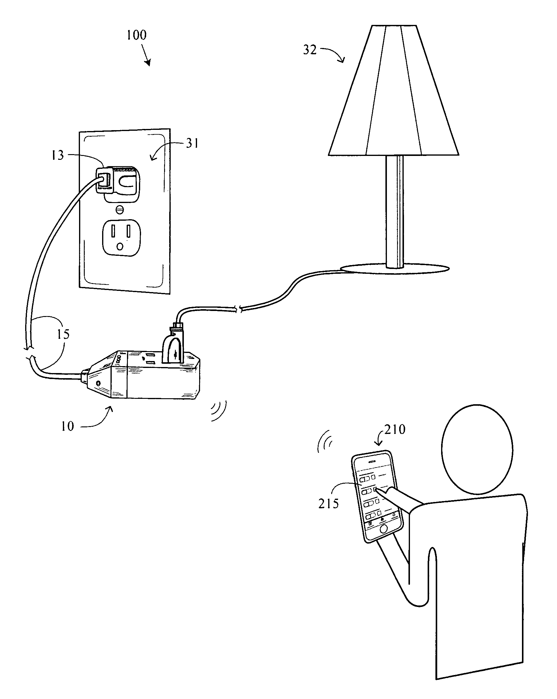
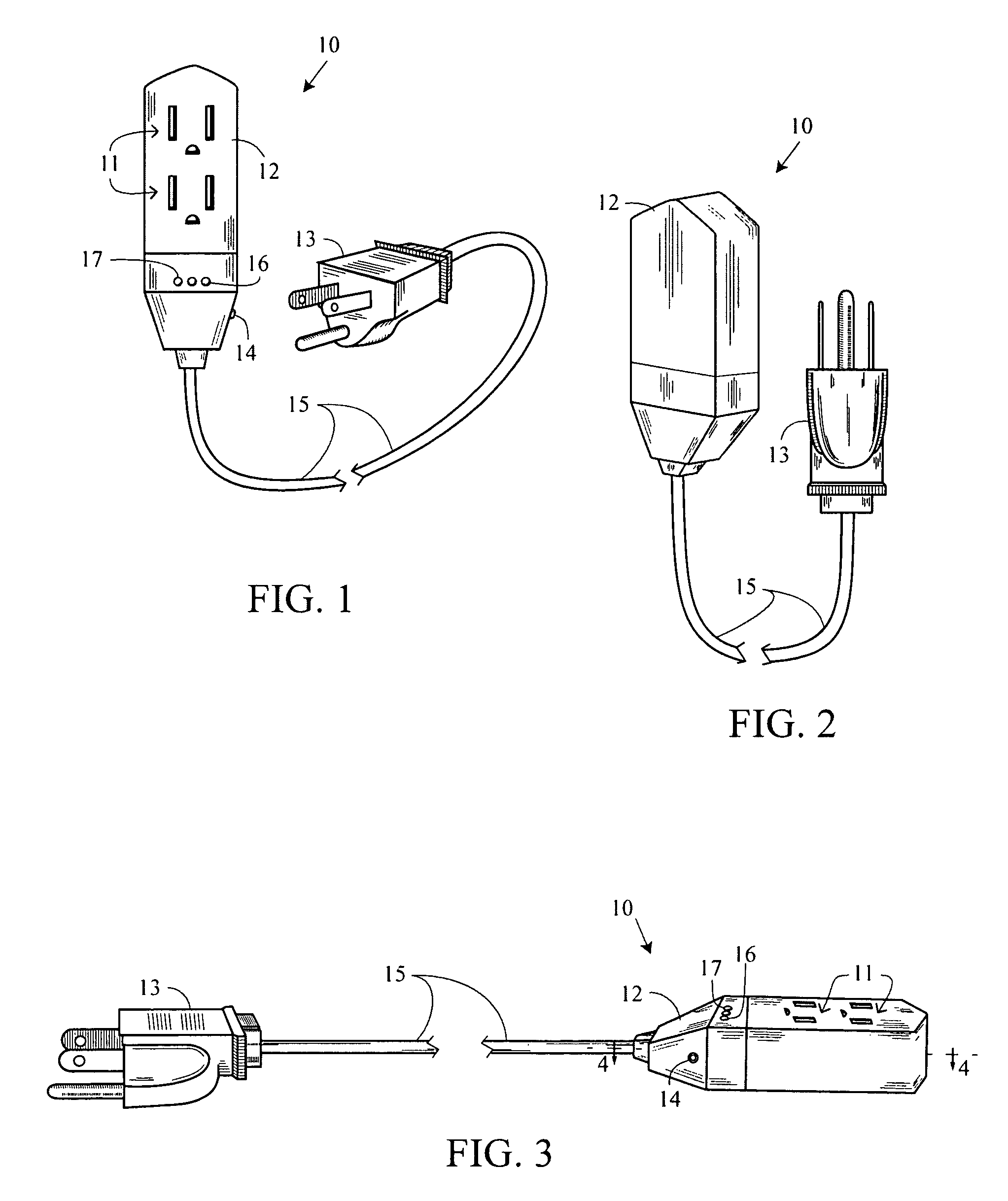
[0049]A preferred embodiment of an apparatus 10 utilized for controlling power to an electrically powered device is shown in FIGS. 1-3, in the form of an extension cord. The apparatus 10 comprises of at least one controlled socket 11, a casing 12, a plug 13, a switch 14, and a cord 15.

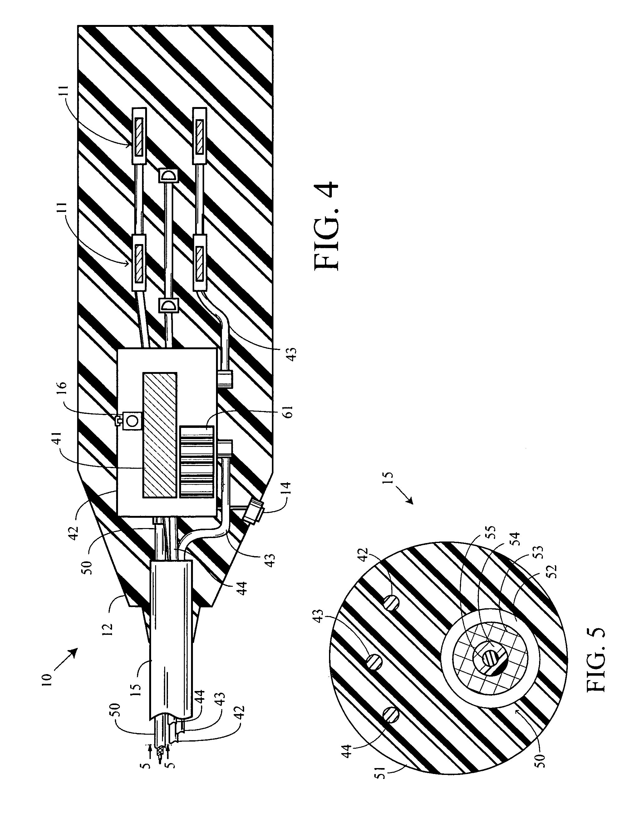
[0050]In FIG. 4, the interior components of the apparatus 10 are shown and in FIG. 6 a circuit block diagram for the apparatus 10 is shown. The apparatus 10 further comprises at least a radio transceiver 50a, a microprocessor 41, a switch 61, and a power converter. Additionally, light-emitting diodes (LED) 16 provide status indication.

[0051]The plug 13 is used to receive alternating current (AC) power, and the switch 61 is connected in between the socket 11 and the plug 13.

[0052]The microprocessor 41 receives direct current (DC) power, decodes a control signal from a remote control, such as a handheld device, via the radio transceiver 50a, and then controls the switch 61 based on the decoded control si...


PUM


Abstract

A system and method for remotely controlling power to an electrically powered device in a simple and efficient manner is disclosed herein. The system comprises an apparatus, an electrically-powered device and a controller. The apparatus comprises a cord, an alternating current outlet socket, an alternating current input plug, a latching relay, a processor and a transceiver. The system preferably uses a WiFi communication signal to transmit commands from the remote controller to the apparatus.

Description

CROSS REFERENCE TO RELATED APPLICATION[0001]Not ApplicableSTATEMENT REGARDING FEDERALLY SPONSORED RESEARCH OR DEVELOPMENT[0002]Not ApplicableBACKGROUND OF THE INVENTION[0003]1. Field of the Invention[0004]The present invention generally relates to controlling power to an electrically powered device. More specifically, the present invention relates to a system and method for controlling power to an electrically powered device.[0005]2. Description of the Related Art[0006]End Users are becoming increasingly empowered to manage and save electrical power in their everyday lives. They understand that small changes in their behavior coupled with the use of smart power saving devices can minimize their power usage and save on their perpetually increasing energy bills. Additionally, End Users are continually searching for ways to have more control and customization over their environment for enhanced aesthetics and personal preferences and convenience.[0007]The prior art discusses various me...

Claims


Application Information

Patent Timeline
IPC IPC(8): H02J3/14
CPCH01R13/665H01R13/70H01R25/003H02J3/14H02J13/0075Y04S40/126Y04S20/16Y02B70/3266Y04S20/242Y02B90/2653Y02B90/226G06F1/266G06F2200/261H02J2310/14H02J13/00026H02J13/00004H02J13/0005Y02B70/30Y02B90/20Y02D10/00Y04S20/222Y02B70/3225Y04S20/00
Inventor PUSCHNIGG, GREGKRUMMEY, MICHAEL
Owner BEST ENERGY REDUCTION TECH
Why Eureka
Try Eureka