Device for moving a body linearly between two predetermined positions

a technology of moving a body and a predetermined position, applied in the direction of magnets, magnets, propulsion systems, etc., can solve the problems of not satisfying the desire for the power supply to be minimized, other solutions suffer from drawbacks, and cannot guarantee the travel tim

Active Publication Date: 2011-06-21
SAFRAN ELECTRONICS & DEFENSE
View PDF30 Cites 17 Cited by
  • Summary
  • Abstract
  • Description
  • Claims
  • Application Information

AI Technical Summary

Benefits of technology

[0009]An essential object of the invention is to satisfy the various requirements of practical use by proposing an improved device which, in particular, is reliable, failsafe, fast, and has low power consumption, and that can be implemented in a compact form.
[0019]A device is thus constituted that satisfies entirely the objects set as regards operating reliability, speed of going from one position to the other, and low power consumption.
[0021]Advantageously, provision is made for the first and second electromagnets to be arranged to operate in opposition so that the core of one of them is in an “out” position in which it stands proud while the core of the other of them is in the “in” position, and vice versa. It is thus possible to guarantee that one of the electromagnets is in the position in which it can develop maximum force and that the device always operates at maximum speed.

Problems solved by technology

Unfortunately, that conventional solution lies in the fact that holding the body in the second position, which requires a constant supply of power corresponding to at least the power supply necessary for the electromagnet to overcome the force generated by the return spring as compressed, which does not satisfy the desire for the power supply to be minimized.
Unfortunately that other solution suffers from drawbacks.
Motor and gearbox units suitable for transforming the movement in rotation of the motor into a movement in translation under a sufficient traction force do not make it possible to guarantee a travel time between the first and second positions that is as short as the travel time procured by an electromagnet.
In addition, implementing a screw-and-nut transmission very significantly reduces the efficiency of the device.
Under such conditions, if additional requirements are added, such as looking for a short stroke that is traveled in as short a time as possible, or looking for a device that occupies a rectangular block shaped space that is as small as possible, or indeed looking for power consumption that is as low as possible in order to remain compatible with a low power source that is shared with a plurality of other vital devices in an overall system, it can be understood that the above-mentioned conventional solutions can in no way satisfy the various and numerous requirements.

Method used


Image

  • Device for moving a body linearly between two predetermined positions
  • Device for moving a body linearly between two predetermined positions
  • Device for moving a body linearly between two predetermined positions

Examples


Embodiment Construction

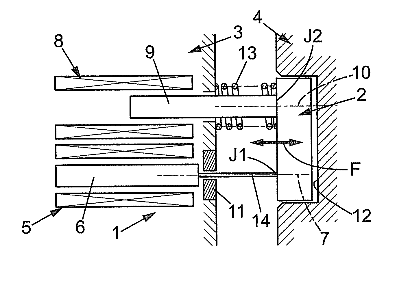
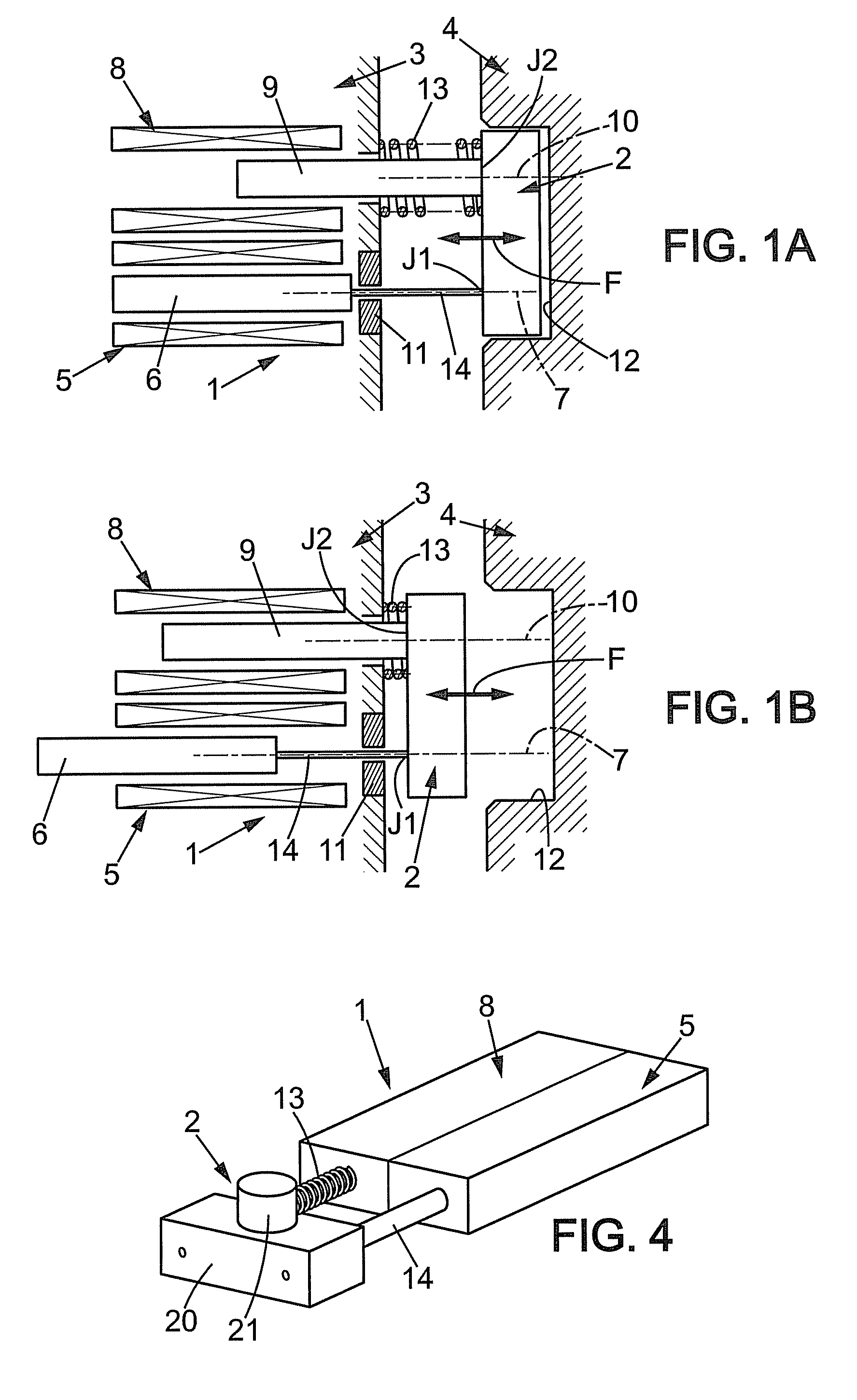
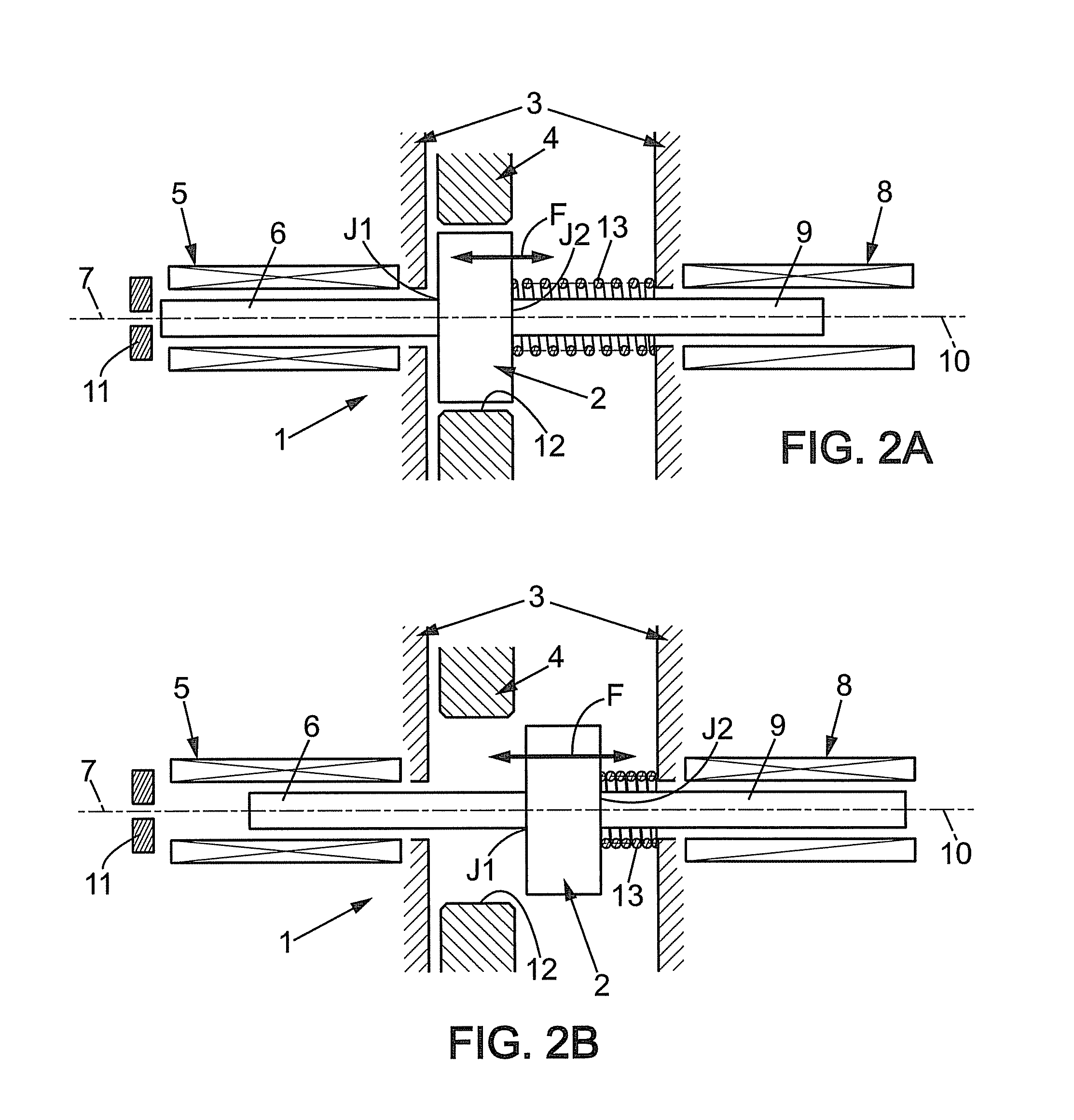
[0029]With reference firstly to FIGS. 1A and 1B, those figures show a preferred embodiment of a device designated overall by reference 1, and suitable for moving a body 2 along a substantially linear path (arrow F) between a first predetermined position (FIG. 1A) and a second predetermined position (FIG. 1B). In order to give some idea, but bearing in mind that this is not the sole application of a device of the invention, the body 2 can be a moving latch making it possible to secure two pars 3 and 4 together (FIG. 1A) or to release them from each other (FIG. 1B), one of which parts can be a stationary part while the other is a moving part that needs to be held stationary on command. For example, the first position (FIG. 1A) can need to be a rest position and a failsafe position that must be taken up in the event of an incident, in particular in the event of an interruption in the electrical power supply.

[0030]The device 1 comprises:[0031]a first electromagnet 5 which has a first mo...


PUM

PropertyMeasurementUnit
DC voltageaaaaaaaaaa
voltageaaaaaaaaaa
lengthaaaaaaaaaa

Abstract

A device (1) suitable for moving a body (2) along a linear path (F) between two predetermined positions, and comprising: first and second electromagnets (5, 8) respectively having first and second moving cores (6, 9) that are secured to the body and that are arranged to have axes of action (7, 10) on the body that are parallel to the path (F), and a permanent magnet (11) associated functionally with the first core (6) and disposed to co-operate magnetically and functionally therewith when the body finds itself in its first position, and preferably return means (13) that are associated with the body so as to urge it back from the second position to the first position when the second electromagnet (8) is not excited.

Description

FIELD OF THE INVENTION[0001]The present invention relates to the field of moving a body in translation, i.e. along a substantially linear path, between first and second predetermined positions.[0002]In particular, the invention relates to moving a body in translation between a stable first position (in particular a rest position) and a second position that requires a constant but minimum supply of power in order to be held. Preferably the stable first position should be a failsafe position, i.e. it should be taken up by the body in the event of a failure in the supply of power required to maintain the second position. Finally, the body can be subjected to load factors and should be capable of being held in the first and the second positions in the presence of such load factors.BACKGROUND OF THE INVENTION[0003]One technical solution to address the problem posed could consist in implementing an electromagnet that is functionally associated with a return spring for returning the body t...

Claims


Application Information

Patent Timeline
Patent Type & Authority Patents(United States)
IPC IPC(8): H01F7/00H01H9/00H01H67/02
CPCH01F7/122H02K33/02H01F7/1615H01F2007/1692
Inventor ROCHE, SYLVAIN
Owner SAFRAN ELECTRONICS & DEFENSE
Why Eureka
Try Eureka