Display method and display device
a display method and display medium technology, applied in the field of display methods and display mediums, can solve the problems of low light usage efficiency, decreased reflection coefficient, and impeded contrast and reflection coefficien
- Summary
- Abstract
- Description
- Claims
- Application Information
AI Technical Summary
Benefits of technology
Problems solved by technology
Method used
Image

Examples
example 1
Preparation of Display Device
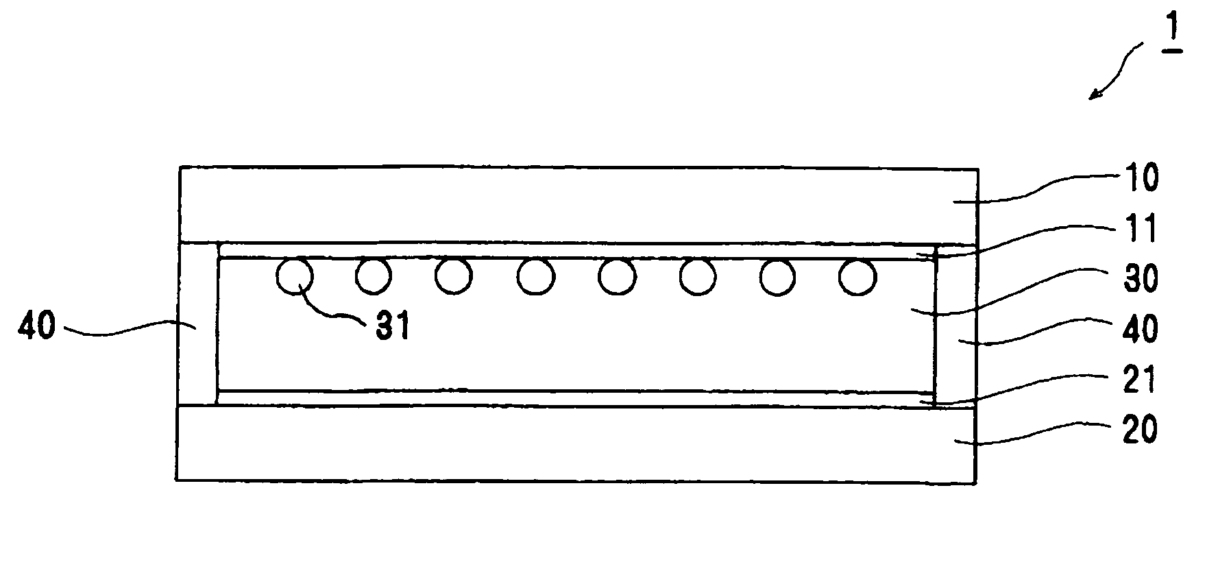
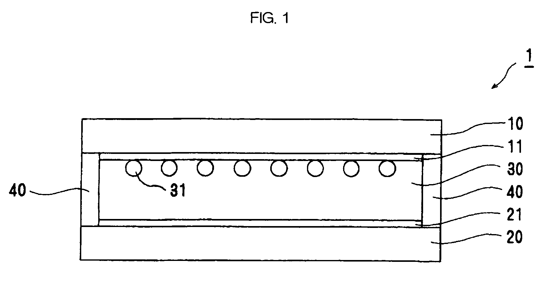
[0105]A display medium having the constitution as shown in FIG. 1 is prepared in the procedures as described below.
[0106]Firstly, a transparent non-alkali glass substrate 10 (thickness: 1 mm, size: 10 cm×10 cm) on one side of which an ITO film (film thickness: 200 nm) is provided as a transparent electrode 11 as a display electrode, is prepared. An area of the display electrode portion is set to be 0.25 cm2.
[0107]On the other hand, tetrabutyl ammonium bromide and lithium perchlorate are dissolved in DMSO (dimethyl sulfoxide) as supporting electrolytes so that the concentration of the tetrabutyl ammonium bromide becomes 0.5 mol / l and that of the lithium perchlorate becomes 0.1 mol / l. 100 parts by mass of the resultant solution is added with 120 parts by mass of titanium oxide and stirred so as to prepare an electrolytic solution 30.
[0108]Next, a spacer having a thickness of 100 μm is provided on an electrode-provided side of the transparent substrate 10 o...
example 2
Preparation of Display Device
[0114]A display medium of Example 2 is prepared ion the same manner as that for Example 1, except that copper is used in place of the gold for the counter electrode 21, tetrabutylammonium bromide is used as the supporting electrolyte, and sodium bromide is used in place of lithium perchlorate so that the concentration of the sodium bromide becomes 0.6 mol / l.
[0115]When the device is observed from the display substrate side, the device looks white. A white reflection coefficient of the device measured by using a Macbeth densitometer (trade name: MACBETH RD-918, described above) is 0.15 (OD).
Evaluation of Display Device
[0116]Evaluations for the display device of Example 2 are carried out in the same manner as in Example 1. A coloration of a display electrode portion of the display device of Example 2 in the former stage is red similarly to Example 1. Further, when the current is excessively flown, the display electrode portion of the display device of Examp...
example 3
Preparation of Display Device
[0121]Chloroauric acid is dissolved in DMSO (dimethyl sulfoxide) so that the concentration thereof becomes 0.5 mol / l. 100 parts by mass of the resultant solution is added with 120 parts by mass of titanium oxide and stirred so as to prepare an electrolytic solution. A display device of Example 3 is prepared in the same manner as in Example 1 except that the thus obtained electrolytic solution is used in place of the electrolytic solution 30.
[0122]When the device is observed from the display substrate side, the device looks slightly-yellow white. A white reflection coefficient of the device measured by using a Macbeth densitometer (trade name: MACBETH RD-918, described above) is 0.39 (OD). When current having a polarity which is reverse to the current which deposits particles is applied so that a gold ion in the electrolytic solution is deposited on a side of a metal electrode, from which the ion is eluted, a white reflection coefficient thereof is measur...
PUM
| Property | Measurement | Unit |
|---|---|---|
| voltage | aaaaa | aaaaa |
| particle size | aaaaa | aaaaa |
| particle size | aaaaa | aaaaa |
Abstract
Description
Claims
Application Information
 - R&D Engineer
- R&D Manager
- IP Professional
- Industry Leading Data Capabilities
- Powerful AI technology
- Patent DNA Extraction
Browse by: Latest US Patents, China's latest patents, Technical Efficacy Thesaurus, Application Domain, Technology Topic.
© 2024 PatSnap. All rights reserved.Legal|Privacy policy|Modern Slavery Act Transparency Statement|Sitemap