Telescoping cavitator

a cavitator and telescopic technology, applied in the field of high-speed underwater projectiles, can solve the problems of tight tolerances that must be maintained, and achieve the effects of reducing drag resistance, maximizing projectile range, and reducing projectile drag resistan

Inactive Publication Date: 2011-06-28
THE UNITED STATES OF AMERICA AS REPRESENTED BY THE SECRETARY OF THE NAVY
View PDF16 Cites 19 Cited by
  • Summary
  • Abstract
  • Description
  • Claims
  • Application Information

AI Technical Summary

Benefits of technology

[0012]It is a further object that the telescoping primary cavitator controllably and smoothly transitions a formed vaporous supercavitation cavity to a secondary cavitator while in flight;
[0014]These objects are accomplished with the present invention by providing a high speed underwater projectile configuration that includes a cylindrical telescoping cavitator design capable of providing projectile nose shape change where such change to the projectile nose tip geometry results in supercavitation and a concomitant vaporous cavity in the water that reduces projectile drag resistance while maximizing projectile range and where the projectile nose tip further includes a retractable cavitator piston feature. The projectile nose is designed to house a cylindrical cavitator piston that protrudes forward from the projectile and is held in place until launch. Velocity induced hydrodynamic forces on the forward face of this cavitator piston cause the piston to start moving aft and to gradually cause the piston to retract into the projectile nose, until a larger, secondary cavitator is exposed to the vaporous cavity.

Problems solved by technology

The difficulty with this fixed geometry approach is that very tight tolerances must be maintained in the location and size of the secondary cavitator 42 for it to be effective.

Method used


Image

  • Telescoping cavitator
  • Telescoping cavitator
  • Telescoping cavitator

Examples


Embodiment Construction

[0021]With reference to the above described drawings wherein like numerals represent like parts throughout the several figures, there is shown a telescoping cavitator piston system in accordance with the teachings of the present invention.

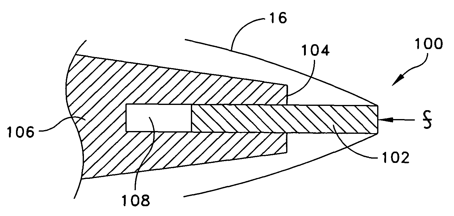
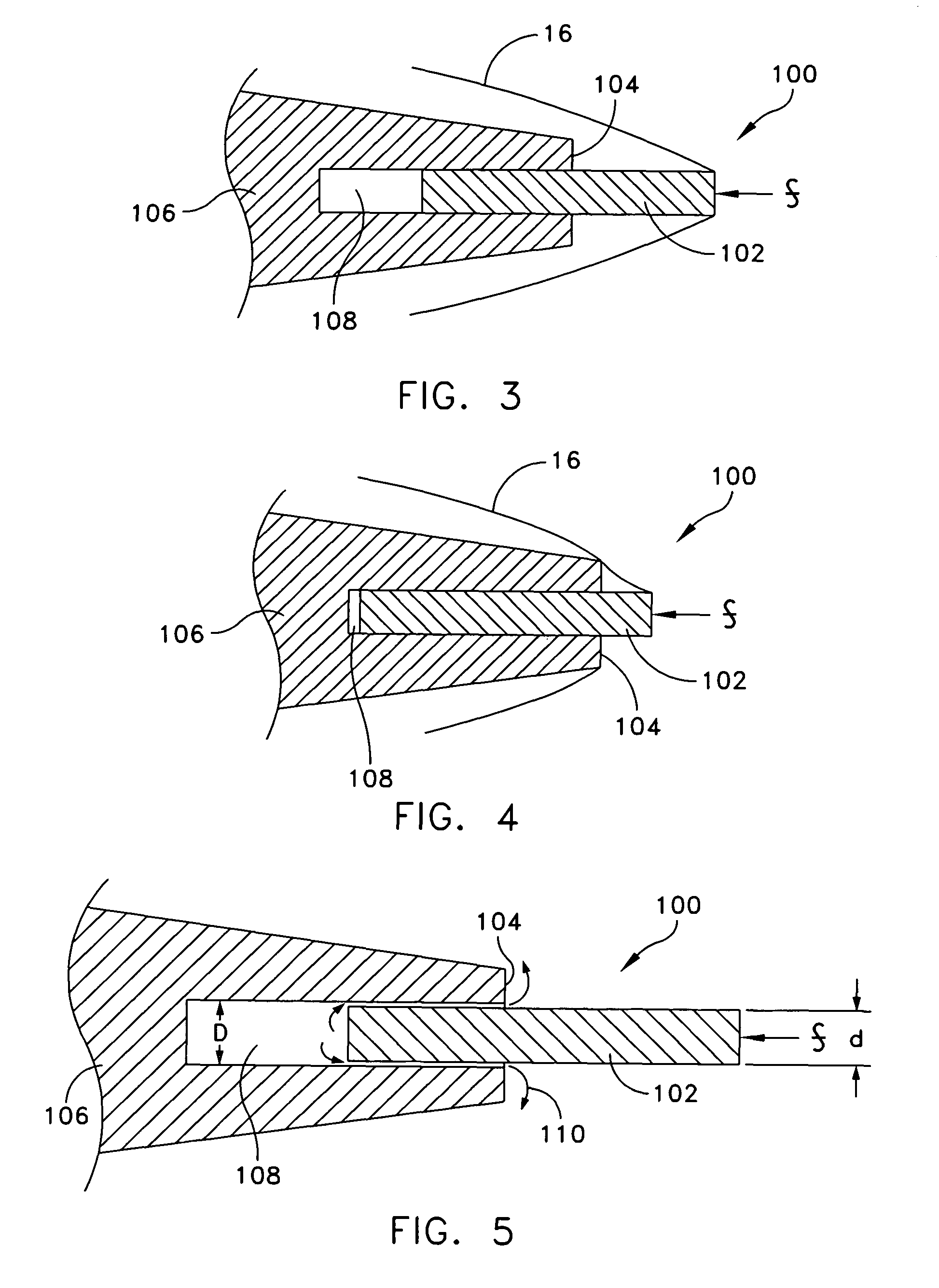
[0022]Rather than relying on the velocity decay of a high speed projectile to engage a secondary cavitator, a variable geometry configuration is now described where the primary cavitator is movable and is allowed to transit backwards at a controlled rate as the projectile travels through the water. The combined action of changes in the forward cavitator geometry and the reduction in size of the vaporous cavity due to projectile slowing induce the secondary cavitator to engage the vaporous cavity at precisely the desired point in the projectile trajectory.

[0023]FIG. 3 illustrates the basic telescoping cavitator design concept generally identified as 100. Initially, a primary cavitator piston 102 extends from the nose 104 of projectile 106 with a por...


PUM


Abstract

A high speed underwater projectile configuration that includes a cylindrical telescoping cavitator design capable of providing projectile nose shape change where such change to the projectile nose tip geometry results in supercavitation and a concomitant vaporous cavity in the water that reduces projectile drag resistance while maximizing projectile range and where the projectile nose tip further includes a retractable cavitator piston feature. The projectile nose is designed to house a cylindrical cavitator piston that protrudes forward from the projectile and is held in place until launch. Velocity induced hydrodynamic forces on the forward face of this cavitator piston cause the piston to start moving aft and to gradually cause the piston to retract into the projectile nose, until a larger, secondary cavitator is exposed to the vaporous cavity.

Description

STATEMENT OF GOVERNMENT INTEREST[0001]The invention described herein may be manufactured and used by or for the Government of the United States of America for governmental purposes without the payment of any royalties thereon or therefor.CROSS REFERENCE TO OTHER PATENT APPLICATIONS[0002]None.BACKGROUND OF THE INVENTION[0003](1) Field of the Invention[0004]The present invention relates to high velocity underwater projectiles and more specifically to an underwater projectile configuration that includes a cylindrical telescoping cavitator piston design capable of changing the shape of the projectile nose where such change to the projectile nose tip geometry results in a controllable supercavitation produced vaporous cavity that reduces projectile drag resistance while maximizing projectile range and where the projectile nose tip further includes a retractable piston feature. The projectile nose is designed to house a cylindrical cavitator piston that protrudes forward from the projecti...

Claims


Application Information

Patent Timeline
Patent Type & Authority Patents(United States)
IPC IPC(8): F42B15/20
CPCF42B14/02
Inventor GIESEKE, THOMAS J.
Owner THE UNITED STATES OF AMERICA AS REPRESENTED BY THE SECRETARY OF THE NAVY
Why Eureka
Try Eureka