Fluid filter support layer

a technology of filter support layer and filter, which is applied in the direction of filtration separation, separation process, bandage, etc., can solve the problems of reducing the flow rate of high-efficiency filters, restricting the flow of fuel at filters, and affecting the flow rate and throughput performance of high-efficiency filters. , to achieve the effect of enhancing and maintaining pleat separation, preventing pleat deformation, and promoting fluid flow

Inactive Publication Date: 2011-06-28
CUMMINS FILTRATION IP INC
View PDF24 Cites 3 Cited by
  • Summary
  • Abstract
  • Description
  • Claims
  • Application Information

AI Technical Summary

Benefits of technology

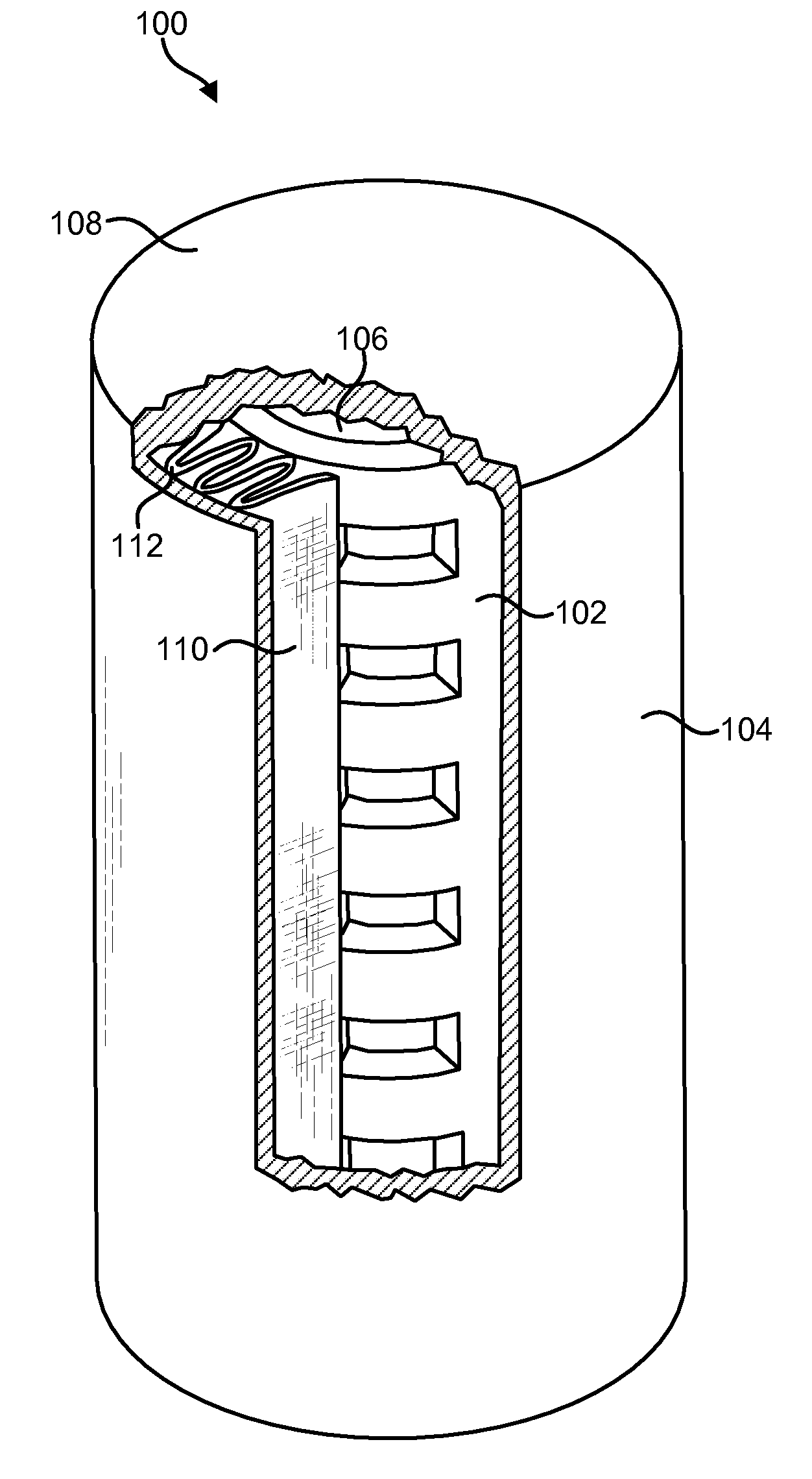
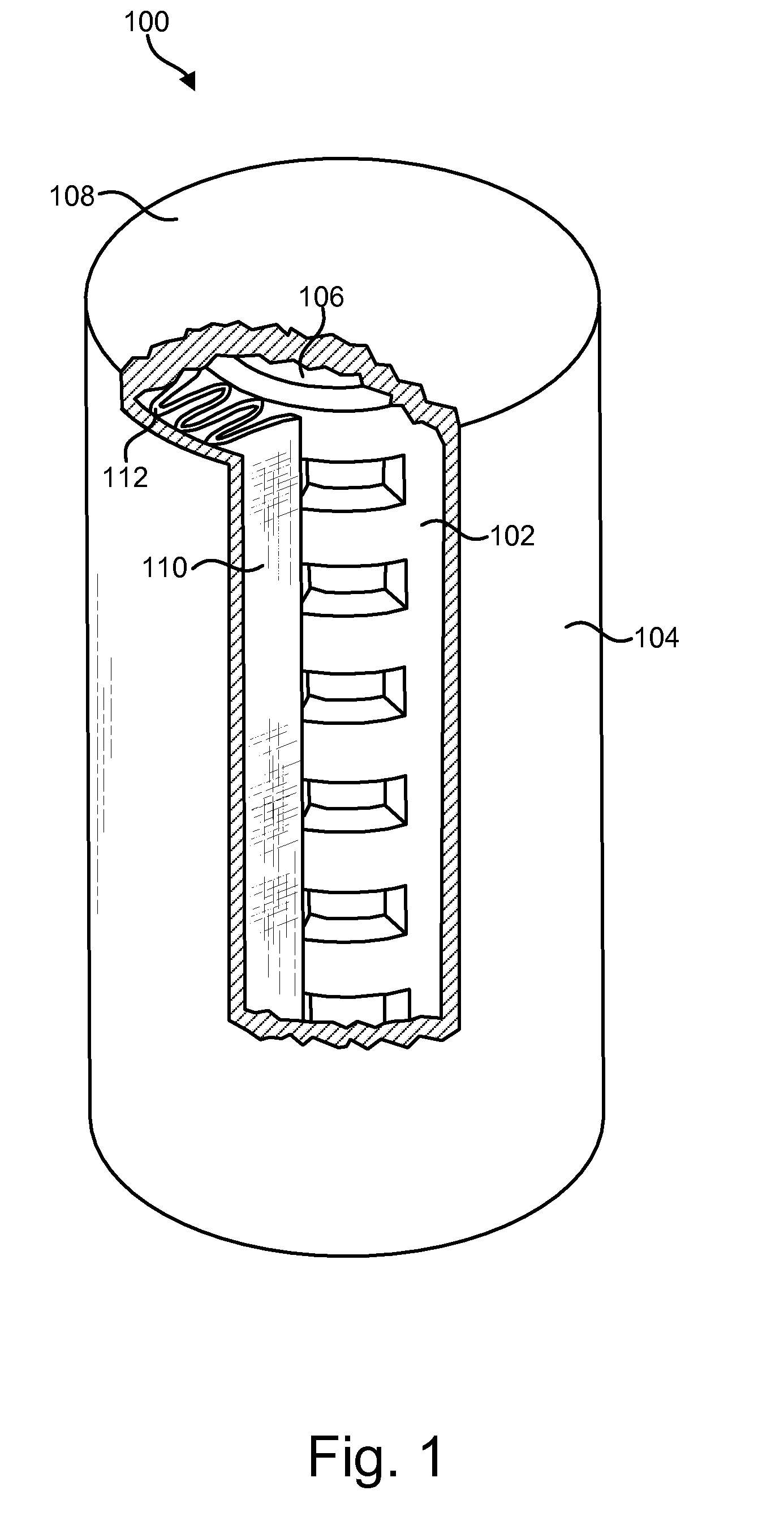
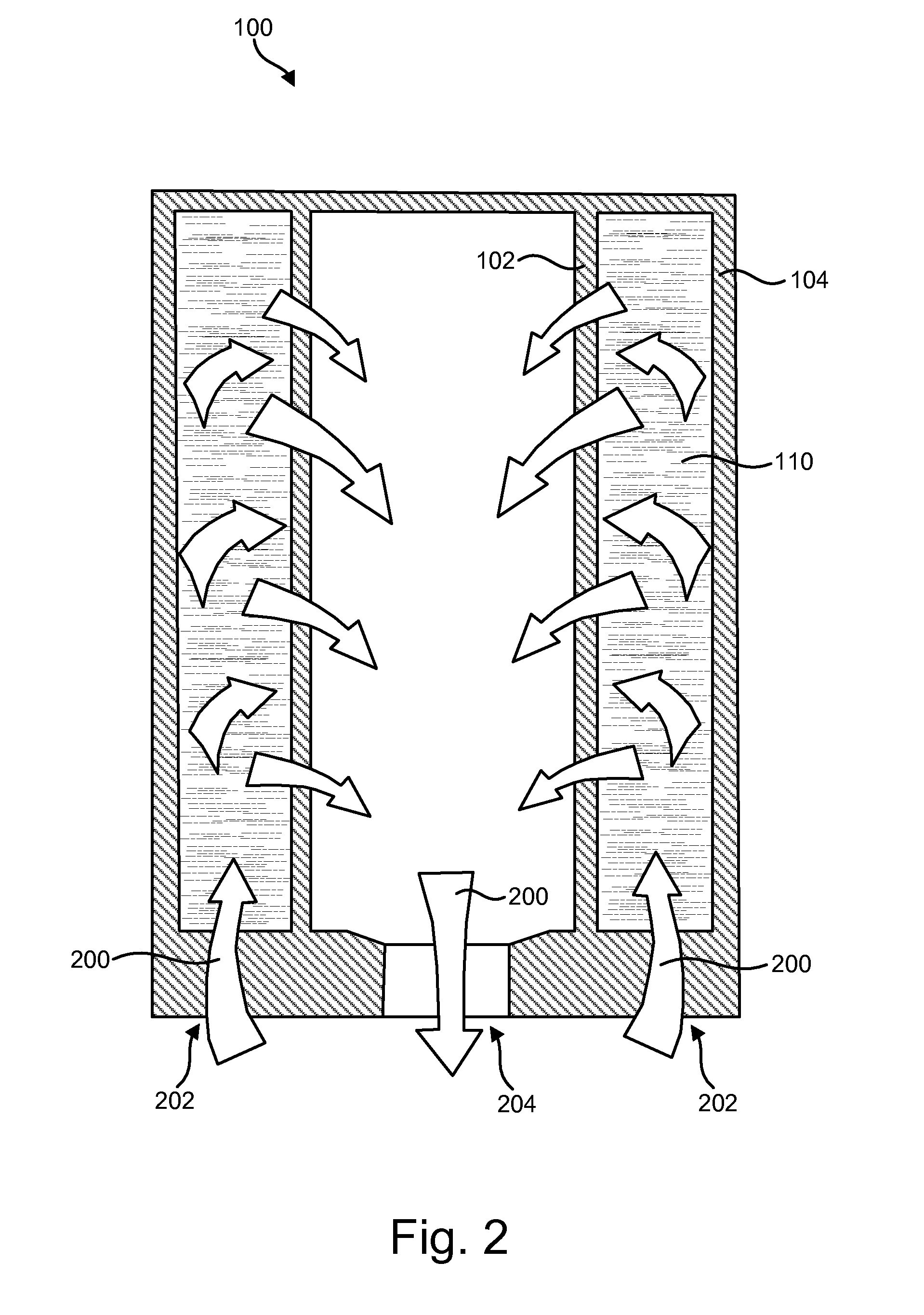
[0015]In some embodiments, the support layer includes a hydroentangled cellulosic material having multiple apertures, where the apertures provide channels to facilitate fluid flow across the filter. The plurality of apertures may occupy between about twenty-five percent and about eighty-five percent of the surface area of the support layer to maximize fluid flow. In one embodiment, a portion of the plurality of apertures is partially occluded by support layer fibers to provide increased structural support to the filtration layer.
[0016]In addition, the hydroentangled cellulosic material may minimize pressure drop across the filter by providing structural separation between filter pleats. In this manner, the hydroentangled cellulosic material may prevent pleat deformation and / or pleat collapse and enable lateral fluid flow.
[0019]In one embodiment, the filter is a composite pleated filter having numerous longitudinally extending pleats. The hydroentangled cellulosic material may include a depth and rigidity sufficient to prevent pleat deformation, enhance and maintain pleat separation, and promote lateral fluid flow. In some embodiments, for example, the depth of the material may be included in a range between about 0.025 inches and 0.050 inches. The rigidity of the material may be defined by a machine-direction (MD) Gurley stiffness in a range between about 1000 and 3000 mg and a cross-direction (CD) Gurley stiffness in a range between about 500 and 1500 mg.

Problems solved by technology

On the other hand, diesel is about eighteen percent (18%) heavier than gasoline, which may cause problems for diesel vehicles not typical of gasoline vehicles.
Particularly, operation in cold weather may cause diesel components to crystallize, thereby restricting fuel flow at the filters.
While diesel additives may modify the size and shape of crystals that precipitate out of the fuel and / or delay their agglomeration at low temperatures to facilitate fuel throughput, high efficiency filters may have a negative effect on flow and throughput performance, particularly under cold weather conditions.
Such high capacity filters may result in restricted flow paths that are inadequate to enable cold flow, particularly in diesel systems.
While a secondary filter may compensate for reduced efficiency by subjecting a small portion of normal oil flow to more efficient media to remove particulate contamination, the potential catastrophic effect of pressure drop is of paramount importance.
These solutions, however, are often both costly to manufacture and difficult to implement.
Indeed, synthetic materials are inherently costly, rendering a support layer made therefrom likewise costly.
Strands of metal used to create a support layer may snag or tangle in the filtration media, delaying production and increasing labor and resources necessary for proper manufacture.
Similarly, stray wire from metal screens may interfere with efficient production by getting caught in the filtration media.
Metal screens may also dull equipment needed to size the support layer to appropriate dimensions.
Further, metal screens are not incinerable and thereby complicate disposal of the filter after use.

Method used


Image

  • Fluid filter support layer
  • Fluid filter support layer
  • Fluid filter support layer

Examples


Embodiment Construction

[0032]Reference throughout this specification to “one embodiment,”“an embodiment,” or similar language means that a particular feature, structure, or characteristic described in connection with the embodiment is included in at least one embodiment of the present invention. Thus, appearances of the phrases “in one embodiment,”“in an embodiment,” and similar language throughout this specification may, but do not necessarily, all refer to the same embodiment.

[0033]Furthermore, the described features, structures, or characteristics of the invention may be combined in any suitable manner in one or more embodiments. In the following description, numerous specific details are disclosed to provide a thorough understanding of embodiments of the present invention. One skilled in the relevant art will recognize, however, that the invention may be practiced without one or more of the specific details, or with other methods, components, materials, and so forth. In other instances, well-known str...


PUM

PropertyMeasurementUnit
depthaaaaaaaaaa
depthaaaaaaaaaa
depthaaaaaaaaaa

Abstract

An apparatus, system and method to facilitate fluid flow across a filter. The apparatus includes a filtration layer coupled to a support layer to form a composite filter. The support layer includes a hydroentangled cellulosic material forming a plurality of apertures. The apertures form channels to facilitate fluid flow across the filter while the support layer provides structural support to the filtration layer to enable lateral flow while preventing pleat deformation and collapse.

Description

BACKGROUND OF THE INVENTION[0001]1. Field of the Invention[0002]This invention relates to filtration systems, and more particularly relates to a support layer for a filter that maximizes fluid flow and throughput performance.[0003]2. Description of the Related Art[0004]Like gasoline, petrodiesel, or simply “diesel,” is typically produced through a refining and distillation process from crude petroleum oils. Diesel, however, contains about eighteen percent (18%) more energy per unit of volume than gasoline. This attribute, along with the greater efficiency of diesel engines, contributes to greater fuel economy in diesel vehicles.[0005]On the other hand, diesel is about eighteen percent (18%) heavier than gasoline, which may cause problems for diesel vehicles not typical of gasoline vehicles. Particularly, operation in cold weather may cause diesel components to crystallize, thereby restricting fuel flow at the filters. While diesel additives may modify the size and shape of crystals ...

Claims


Application Information

Patent Timeline
Patent Type & Authority Patents(United States)
IPC IPC(8): B01D27/06B01D24/00
CPCB01D29/21B01D2201/04
Inventor MUSE, ROBERT E.STUART, JAMES O.
Owner CUMMINS FILTRATION IP INC
Why Eureka
Try Eureka