
Supporting structure having function of rod-linkage latching

a technology of supporting structure and latching, which is applied in the direction of stand/trestle, kitchen equipment, show hangers, etc., can solve the problems of occupying extra space, occupying ascent/descent, forward/backward movement of flat panel monitors, etc., and achieves the effect of reducing the volume of materials

Inactive Publication Date: 2011-06-28
JARLLYTEC CO LTD
View PDF9 Cites 12 Cited by
  • Summary
  • Abstract
  • Description
  • Claims
  • Application Information

AI Technical Summary

Benefits of technology

The present invention provides a supporting structure with a rod-linkage latching device that allows for adjusting the tilting angle of a connecting unit with respect to a base seat and forming a locking status with a certain angle between the connecting unit and the base seat. The latching device includes a resilient unit and a latching member that can elastically contact a tenon sheet and a releasing member that can press the resilient unit. The latching member is provided in an inner end of a rod-shaped latching member that can elastically in contact with the tenon sheet and form a locking status. The latching member is designed to provide a secure and energy-saving locking status when the connecting unit is adjusted towards the base seat. The supporting structure also includes a rod-linkage mechanism composed of top and bottom connecting rods that can pivotally connect to the base seat and the main supporting rack, and a tenon sheet that can move simultaneously with the base seat to reduce material volume.

Problems solved by technology

But the described fashion can not provide functions of ascent / descent and forward / backward movement to the flat panel monitors.
But during hanging or packaging and conveying the supporting structure, the tilting status of the connecting unit would result in occupying extra space; if the connecting unit is forced to rotate toward the base seat and being positioned, the elastic forces of the torsion springs are needed to be overcome.

Method used


Image

  • Supporting structure having function of rod-linkage latching
  • Supporting structure having function of rod-linkage latching
  • Supporting structure having function of rod-linkage latching

Examples


Embodiment Construction

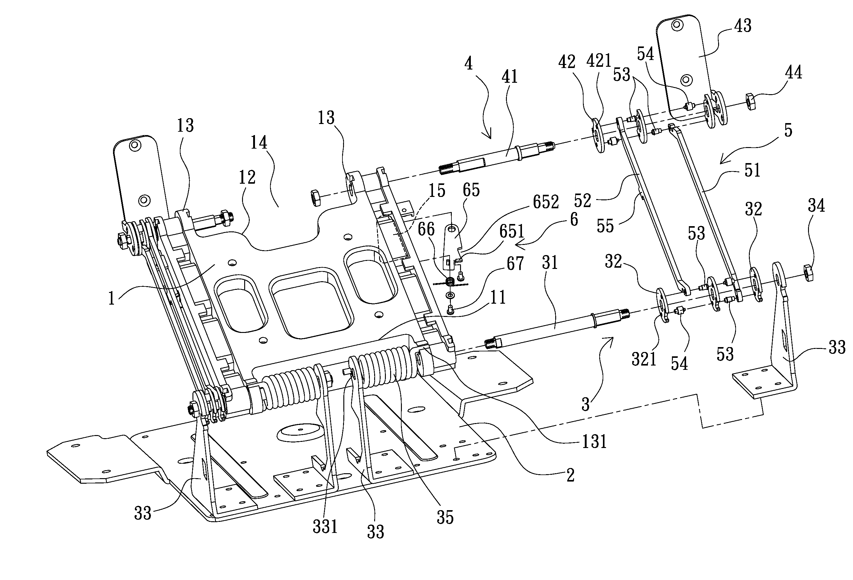
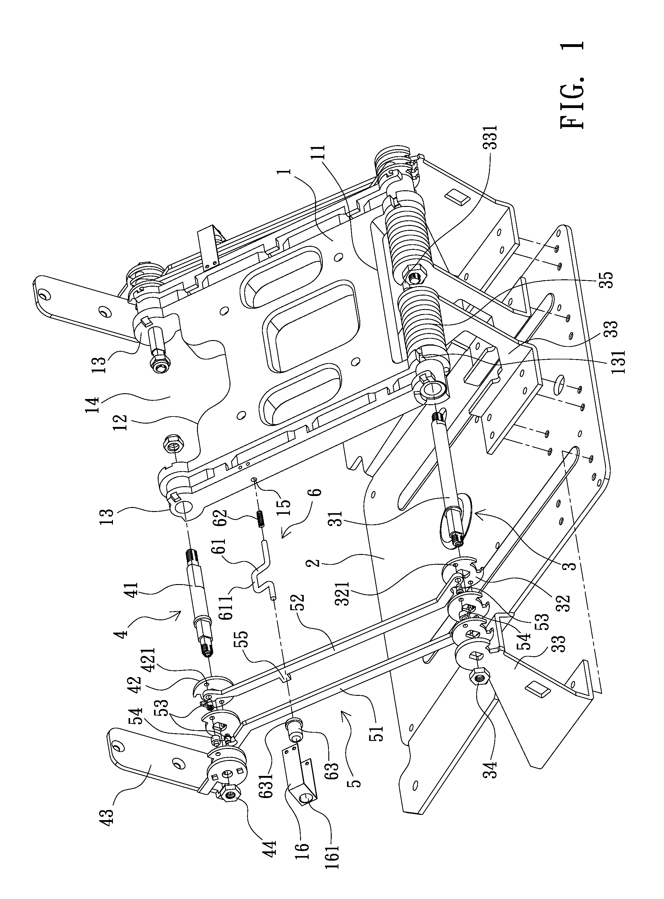
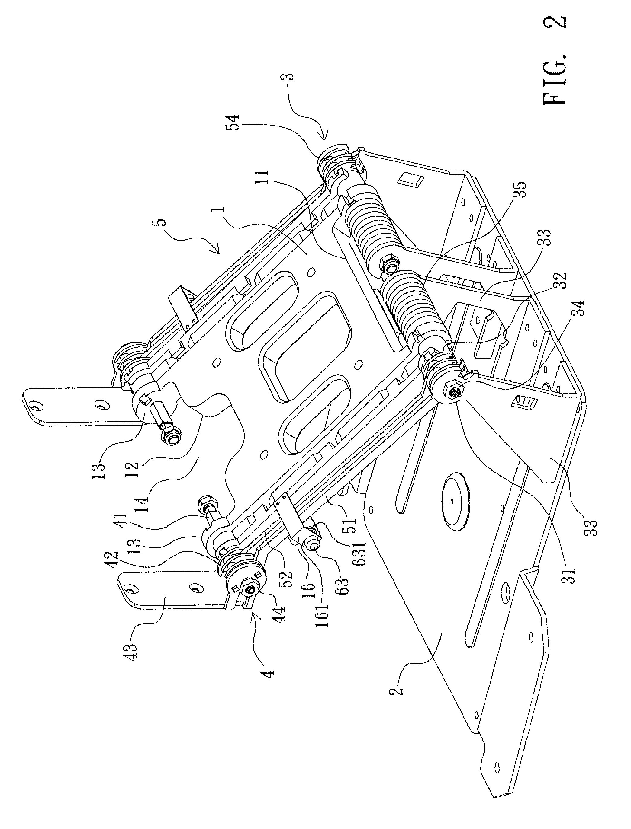
[0023]As shown in FIG. 1 and FIG. 2, the supporting structure provided by the present invention mainly comprises a connecting unit 1, a base seat 2, a base seat hinge 3, a main hinge 4, at least one rod-linkage mechanism 5 and at least one rod-linkage latching device 6.

[0024]The connecting unit 1 is a sheet member, a bottom end 11 and a top end 12 are respectively provided at the bottom and the top of the connecting unit 1 and by pivotally and respectively connecting the base seat hinge 3 and the main hinge 4 to the base seat 2 and an object to be supported e.g. a flat panel monitor, a swingable status is obtained. As shown in FIG. 1, a pair of lugs 13 is respectively extended from two lateral ends of the top end 12 and the bottom end 11, and each pair of the lugs 13 individually has a concave section 14.

[0025]The base seat 2 is a flat-sheet member pivotally connected to the connecting unit 1 by the base seat hinge 3, so the tilt angle of the connecting unit 1 can be adjusted with r...


PUM


Abstract

The present invention relates to a supporting structure having function of rod-linkage latching which comprises a connecting unit, a base seat, a base seat hinge, a main hinge, at least one rod-linkage mechanism and at least one rod-linkage latching device. By providing a rod-linkage latching device between a connecting unit and a rod-linkage mechanism the two connecting rods of the rod-linkage mechanism generate a relative movement while the connecting unit performs tilt angle adjusting toward the base seat, so a tenon sheet of one connecting rod is moved and a latching member of the rod-linkage latching device loses stop and extends then the movement of the tenon sheet is limited thus a locking status is formed, so a torsion spring disposed between the connecting unit and the base seat is pressed so an energy saving status is formed, therefore the connecting unit has a certain angle with respect to the base seat and an advantage of saving volume while packaging and conveying is achieved, and the supporting structure provided by the present invention can be disposed vertically or be hanged.

Description

BACKGROUND OF THE INVENTION[0001]1. Field of the Invention[0002]The present invention relates to a supporting structure, more particularly to a supporting structure having function of rod-linkage latching, a rod-linkage mechanism is latched or released by a rod-linkage latching device so as to suppress or release an elastic force of a torsion spring disposed between a connecting unit and a base seat.[0003]2. Description of Related Art[0004]Flat panel monitors, e.g. liquid crystal monitors, liquid crystal displays or plasma TVs, have advantages of light in weight, thin and no radiation, etc., and are used to replace conventional CRT monitors. When viewing, the liquid crystal and the plasma monitors have limitations of viewing angles, so a structure of rotation shaft is often provided between the an above mentioned monitor and a base seat for providing a function of adjusting elevation angle of the monitor, with respect to the base seat.[0005]But the described fashion can not provide ...

Claims


Application Information

Patent Timeline
Patent Type & Authority Patents(United States)
IPC IPC(8): A47F5/12A47G29/00
CPCF16M11/04F16M11/10F16M11/24F16M13/02F16M11/2092F16M2200/044Y10S248/922Y10S248/917
Inventor HSU, YU-TSUN
Owner JARLLYTEC CO LTD
Learn More