Portable electronic device mount

a technology for electronic devices and mechanical mounts, which is applied in the direction of machine supports, electrical apparatus casings/cabinets/drawers, instruments, etc., can solve the problems of ineffective sealing or attaching of mounts, limited positional capability, and prior mounts with drawbacks, etc., to achieve convenient carrying and storage of mounts and small form factors

Active Publication Date: 2011-06-28
HARMAN INT IND INC
View PDF6 Cites 10 Cited by
  • Summary
  • Abstract
  • Description
  • Claims
  • Application Information

AI Technical Summary

Benefits of technology

[0007]A portable electronic device mount provides a secure attachment point for a personal navigation device, or other electronic device. The mount connects to an attachment mechanism that firmly and reliably attaches the mount to a windshield or other surface. The mount also includes a flexible linkage through which the mounted device may be securely oriented in a wide range of positions. A collapsible arm system helps achieve a small form factor for convenient carrying and storage of the mount.
[0009]The mount may include multiple locking tabs. In one design, two locking tabs are provided on the back rest, and the locking tabs are positioned on opposite sides of and adjacent to the electronics interface. In addition, vibration dampers on the backrest may help reduce mechanical rattling when the device is inserted into the mount. The vibration dampers may be placed above and adjacent the locking tabs, or in other locations. The electronics interface may be a two dimensional pin array. The pins may be individually spring-loaded conductive pins arranged to press against exposed contact pads on the electronic device, when the electronic device is inserted into the mount.
[0010]The mount may also include a socket behind the backrest and a ball disposed in the socket. A spring in the socket biases the ball against the socket to help the mount retain the position set by the user. The spring may be a flat spring, formed from sheet metal or other resilient material.
[0011]An attachment mechanism for the mount securely connects the mount to a surface, such as a windshield. The attachment mechanism may include a support structure defining a chamber and a sealing structure, a deformable membrane covering the chamber and extending beyond the sealing structure, and a piston in the support structure and coupled to the deformable membrane. A piston lever is coupled to the piston and, when depressed, displaces the piston and draws the membrane into the chamber. The result is a vacuum seal against the mounting surface (e.g., the windshield). A flange coupled to the membrane assists with moving or removing the mount from the mounting surface.

Problems solved by technology

However, prior mounts had drawbacks.
In some cases, the mounts did not seal or attach effectively, because of, as one example, an unreliable connection to a windshield.
In other cases, the mounts had limited positional capability, making it difficult to position the portable electronic device precisely where desired.
Furthermore, prior mounts were often bulky to carry and store, and were plagued by loose connections that permitted the portable electronic device to rattle while attached to the mount.

Method used


Image

  • Portable electronic device mount
  • Portable electronic device mount
  • Portable electronic device mount

Examples


Embodiment Construction

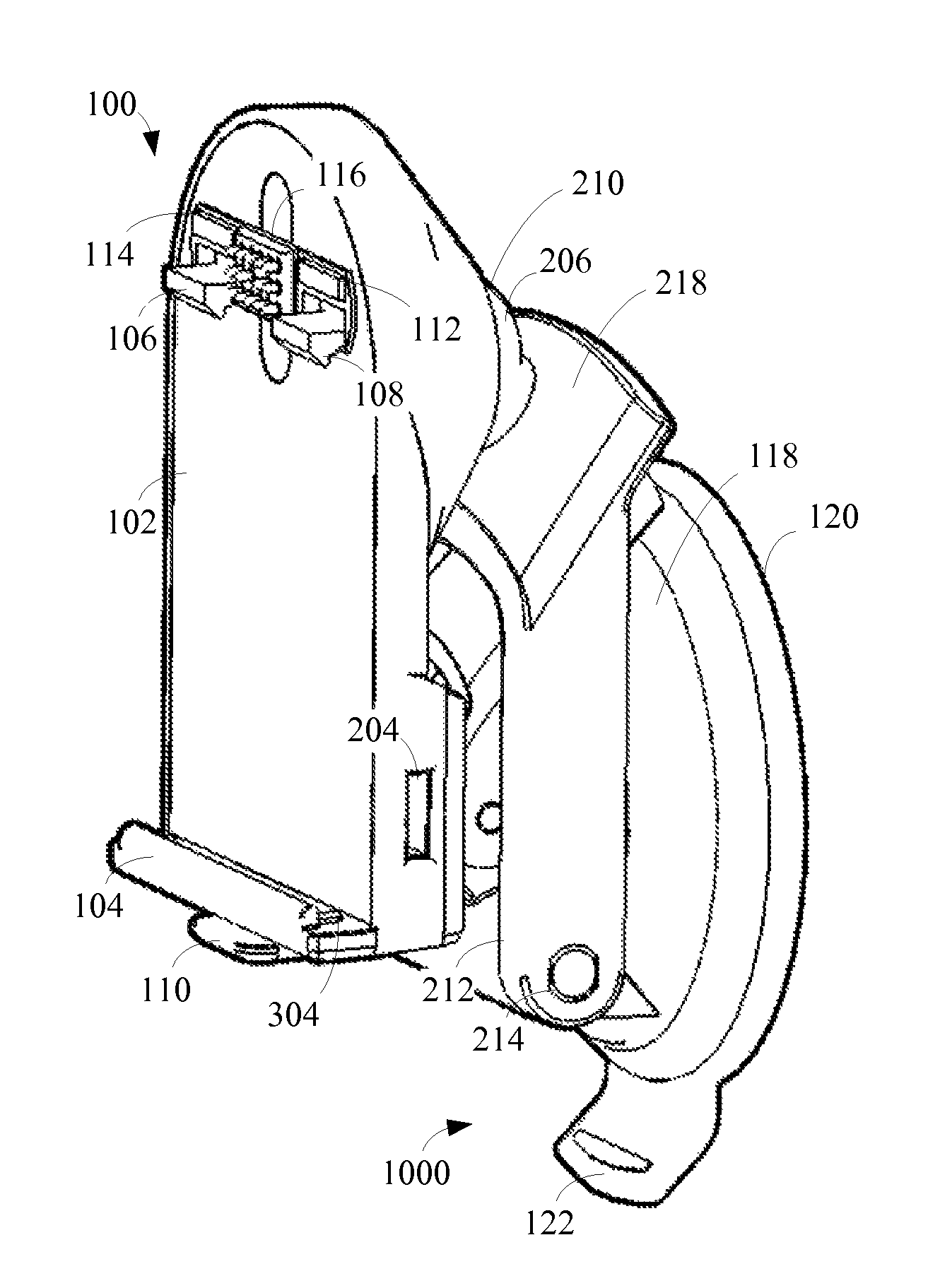
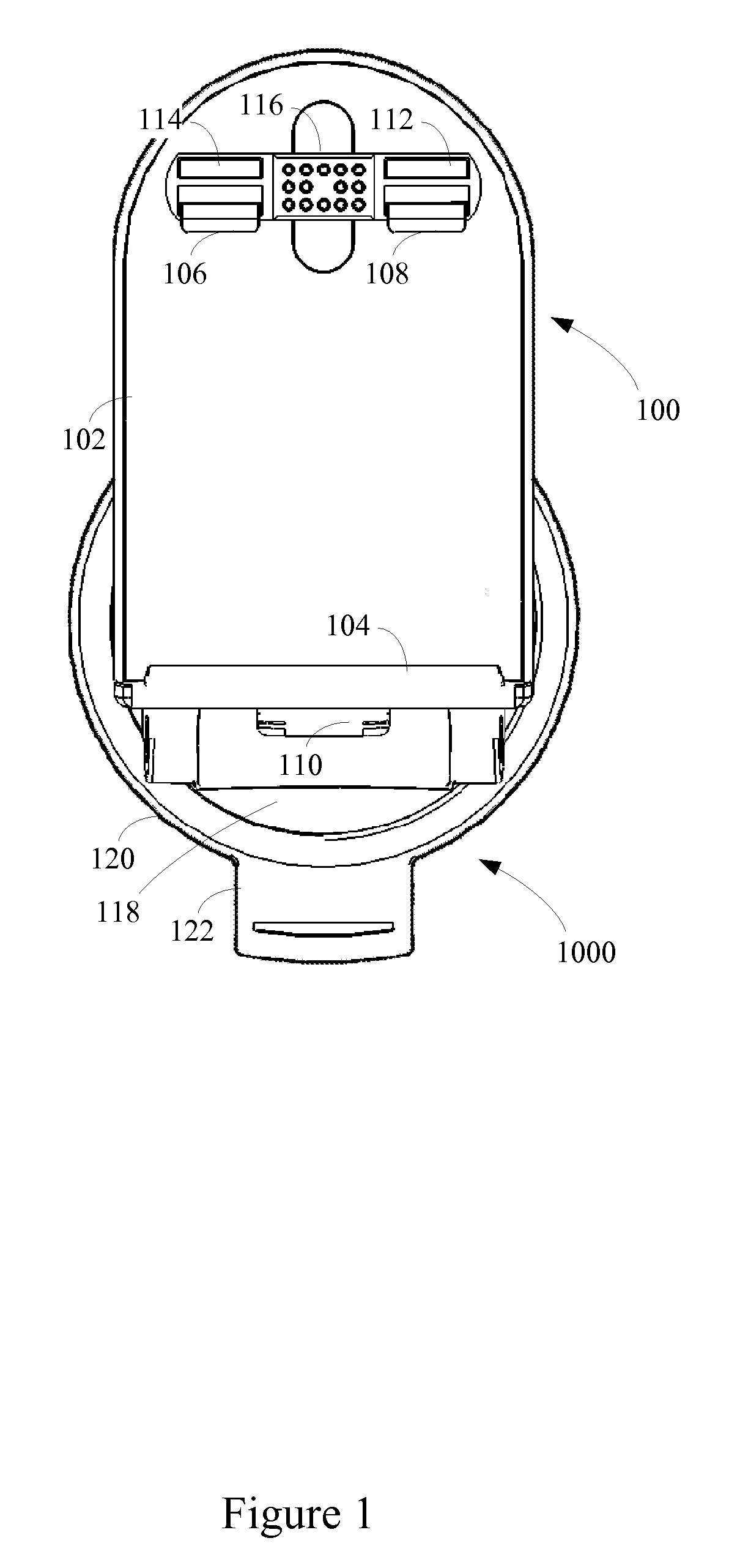
[0032]FIG. 1 shows a top view of a portable electronic device mount (“mount”) 100 and attachment mechanism 1000. The mount 100 includes a backrest 102 against which a portable electronic device may sit when secured into the mount 100. The backrest 102 includes a mating guide 104, a first locking tab 106, a second locking tab 108, and a lock release button 110. A lock release mechanism (described below) connects the lock release button 110 and the locking tabs 106 and 108. The lock release button 110 and mating guide 104 are disposed near the bottom side of the backrest 102, while the locking tabs 106 and 108 are disposed opposite, near the top side of the backrest 102. The lock release button 110 and locking release tabs 106 and 108 may be located in other spatial relationships and in other locations on the backrest 102. The spatial relationship shown in FIG. 1 facilitates convenient and ergonomic one-handed insertion and removal of the portable electronic device.

[0033]The mount 100...


PUM


Abstract

A portable electronic device mount provides a secure attachment point for a personal navigation device, or other electronic device. The mount provides access to the device electronics through interface ports and feature connectors. The mount connects to an attachment mechanism that firmly and reliably attaches the mount to a windshield or other surface. The mount also includes a flexible linkage through which the mounted device may be securely oriented over a wide range of positions. In addition, extendible and retractable extension arms help achieve a compact form factor for convenient carrying and storage of the mount.

Description

BACKGROUND OF THE INVENTION[0001]1. Technical Field[0002]This disclosure relates to a mechanical mount for a portable electronic device.[0003]2. Related Art[0004]Rapid developments in modern technology have led to the widespread adoption of sophisticated portable electronic devices. These devices include personal navigation devices (PNDs), music players, satellite radio receivers, and other devices. Manufacturers have also produced ergonomic mounts into which the device may be secured. For example, a PND may have a mount that attaches to the windshield of a vehicle and that permits the driver to readily view the PND while driving.[0005]However, prior mounts had drawbacks. In some cases, the mounts did not seal or attach effectively, because of, as one example, an unreliable connection to a windshield. In other cases, the mounts had limited positional capability, making it difficult to position the portable electronic device precisely where desired. Furthermore, prior mounts were oft...

Claims


Application Information

Patent Timeline
Patent Type & Authority Patents(United States)
IPC IPC(8): A45D42/14
CPCB60R11/02B60R2011/008B60R2011/0056B60R11/0241
Inventor O'BRIEN, DARREN KELLYLAU, DANNIE C.
Owner HARMAN INT IND INC
Why Eureka
Try Eureka