
Fuse assembly with integrated current sensing

a current sensing and fuse assembly technology, applied in the direction of basic electric elements, electrical equipment, emergency protective devices, etc., can solve the problems of mechanical complexity, shunt resistors have their own limitations, and the accuracy of hall effect sensors is less than the equivalent current shunt methodology, so as to reduce the additional impedance into the drive system, the effect of simple design and manufacturing

Inactive Publication Date: 2011-06-28
ENERDEL
View PDF22 Cites 12 Cited by
  • Summary
  • Abstract
  • Description
  • Claims
  • Application Information

AI Technical Summary

Benefits of technology

"The present invention provides a fuse assembly for electric vehicle drive systems that is simple and easy to manufacture. The fuse assembly includes a main component partially encased in a protective sheath, with connectors for electrical connection and a fusible link for overcurrent protection. A current sensing element is also included, which allows for easy measurement of current flow through the fuse assembly. The current sensing element is maintained within tolerances, and a linking piece is used to connect the fusible link and the current sensing element. The fuse assembly reduces additional impedance in the drive system and is designed to be easily replaced in the event of a short circuit."

Problems solved by technology

With the electrification of the drive systems of vehicles, there are several problems with the state of the art in current sensing methodologies.
Hall effect sensors have three primary problems.
First, the sensors rely on sensing a static magnetic field.
Second, depending on the design, Hall effect sensors are sensitive to the mechanical mounting of the system and can exhibit variations based on their installation methods.
Third, Hall effect sensors are less accurate than equivalent current shunt methodologies.
Inline current shunt resistors have their own limitations.
Second, it is necessary to physically insert the resistance of the current shunt resistor into the current path.
This both adds to the mechanical complexity, and adds additional impedance into the drive system.
Third, if the shunt becomes thermally stressed due to an over current conditions, its electrical resistance changes.

Method used


Image

  • Fuse assembly with integrated current sensing
  • Fuse assembly with integrated current sensing

Examples


Embodiment Construction

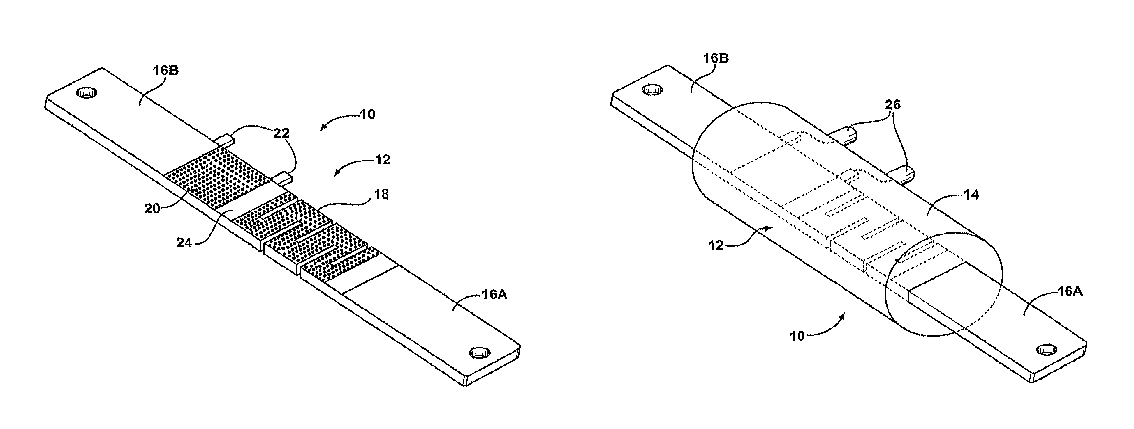
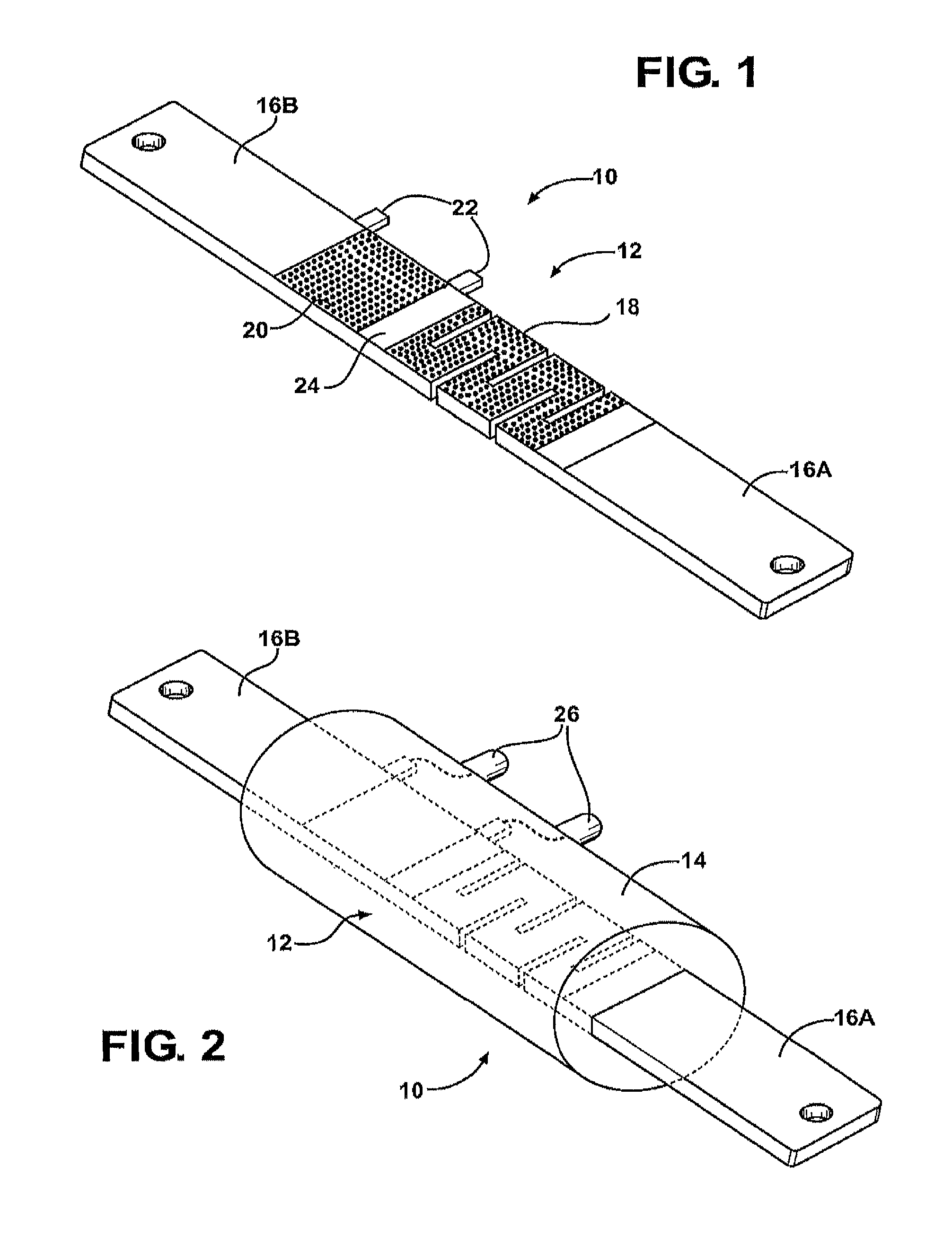
[0018]Referring to the Figures, wherein like numerals indicate corresponding parts throughout the several views, a fuse assembly with integrated current sensing is shown at 10.

[0019]As shown in FIG. 1, the fuse assembly 10 includes a main component 12. Preferably, as shown in FIG. 2, the main component 12 is partially encased in a protective sheath 14 formed of an electrically insulating, i.e., non-conductive, material.

[0020]The main component 12 includes a pair of connectors 16A, 16B formed of an electrically conductive material, such as a metal. The connectors 16A, 16B allow the fuse assembly 10 to be electrically connected into a larger system (not shown), such as an electric vehicle drive system (not shown).

[0021]A fusible link 18 is electrically connected between the connectors 16A, 16B and is preferably encased in the protective sheath 14. The fusible link 18 melts or otherwise dissipates when subjected to current flowing through the fuse assembly 10 in excess of a predetermin...


PUM


Abstract

A fuse assembly includes a main component partially encased in a protective sheath. The main component includes a pair of connectors formed of an electrically conductive material to allow the fuse assembly to be electrically connected into an electric vehicle drive system. A fusible link is electrically connected between the connectors and is preferably encased in the protective sheath. The fusible link reacts to current flowing through the fuse assembly in excess of a predetermined current for a predetermined time, as is well known to those skilled in the art.

Description

RELATED APPLICATIONS[0001]This application is a non-provisional patent application that claims priority to a provisional application Ser. No. 60 / 989,977 filed on Nov. 14, 2007 and incorporated herewith by reference in its entirety.BACKGROUND OF THE INVENTION[0002]1. Field of the Invention[0003]The subject invention relates to a fuse assembly with integrated current sensing, primarily for use in the drive system of an electric or hybrid-electric vehicle.[0004]2. Description of the Related Art[0005]With the electrification of the drive systems of vehicles, there are several problems with the state of the art in current sensing methodologies. Given the high currents present and the need to sense the DC current, there are basically two options: (1) Non-contact Hall effect sensors or (2) Inline current shunt resistors.[0006]Hall effect sensors have three primary problems. First, the sensors rely on sensing a static magnetic field. This static magnetic field can be affected by an external...

Claims


Application Information

Patent Timeline
Patent Type & Authority Patents(United States)
IPC IPC(8): H01H85/04
CPCH01H85/0241H01H2085/0266H01H85/055G01R1/203
Inventor HARTZOG, CHAD
Owner ENERDEL
Learn More