
Display control system, operation input apparatus, and display control method

a control system and display control technology, applied in the field of display control systems, can solve the problems of inconvenient inability to view the navigation screen, and inability to afford the installation of two lcds, and achieve the effect of improving layout freedom

Inactive Publication Date: 2011-06-28
ALPINE ELECTRONICS INC
View PDF15 Cites 20 Cited by
  • Summary
  • Abstract
  • Description
  • Claims
  • Application Information

AI Technical Summary

Benefits of technology

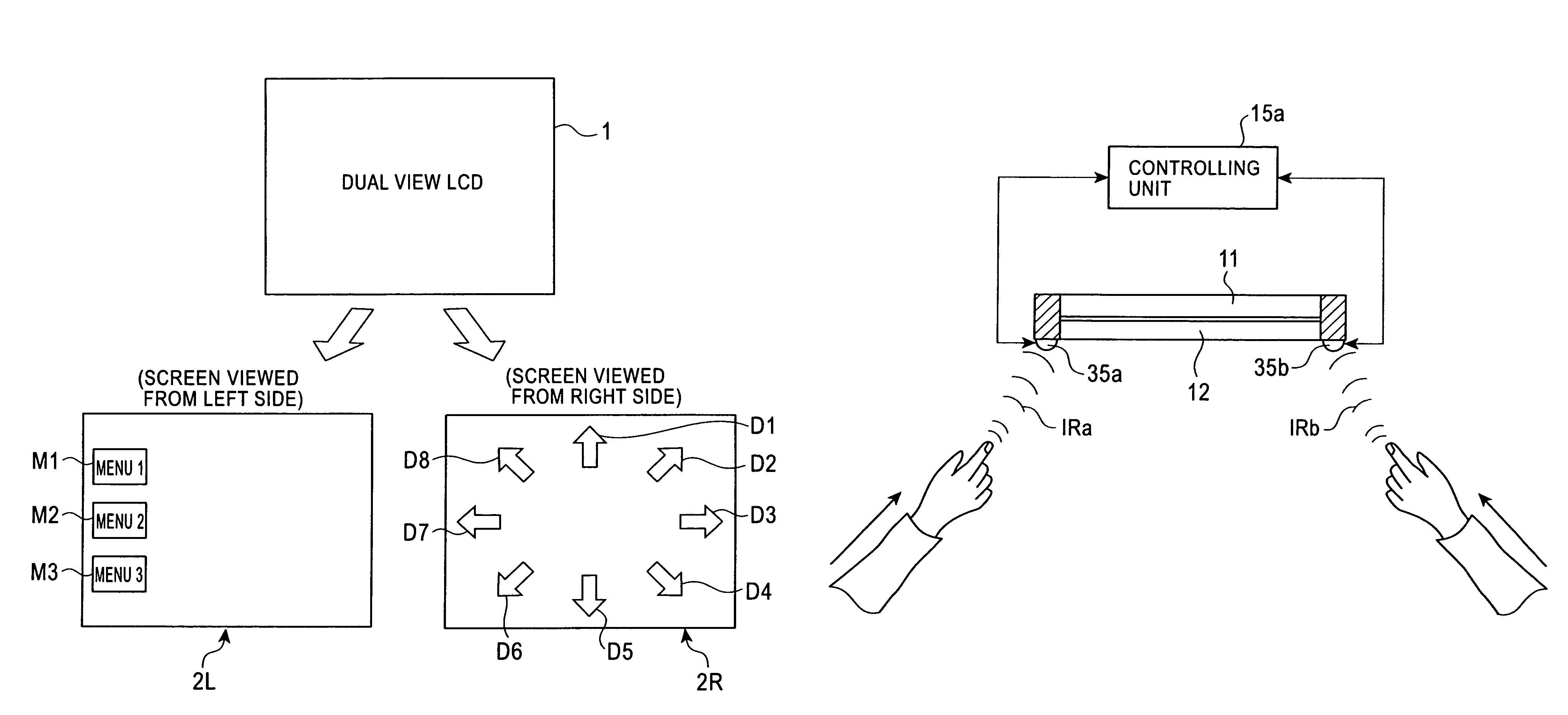
[0014]The present invention has been made in view of the problems of the related art, and an object of the present invention is to provide a display control system that can precisely determine from which side an operator viewing the screen performed an operation and that can display, on the screen, an appropriate image corresponding to an operation entered from the corresponding side, regardless of the layout of operation buttons.
[0016]According to the display control system of the present invention, the operation-input direction identification portion can identify from which of the left and right sides a viewer touched the screen of the display unit (i.e., performed operation input). Thus, without caring about the positions (layout) of operation buttons, it is possible to freely design the screen. In other words, no matter which position an operation button is arranged (i.e., an improvement in layout freedom), the controlling unit cooperates with the operation-input-direction identification portion to thereby make it possible to precisely identify from which of the left and right sides the operation button was operated. Based on the result, appropriate images corresponding to an operation entered from a corresponding side can be displayed on screen of the display unit.

Problems solved by technology

Thus, when the navigation screen is viewed, the A / V screen cannot be viewed, and when the A / V screen is viewed, the navigation screen cannot be viewed.
Further, when the vehicle is moving, a still-image screen such as a navigation screen or the like can be viewed, but a moving-image screen such as a TV screen or DVD screen cannot be viewed in order to ensure safety.
With this configuration, since the TV screen or the like cannot be viewed when the vehicle is moving, it is inconvenient for a person in the passenger seat.
However, except for some expensive large vehicles, the installation of two LCDs cannot be afforded since the space of typical vehicle cabins is limited.
In this case, although there is no problem when he or she can continue to view the TV screen or the like that has been pre-set, it is practically unreasonable for the passenger in the passenger seat to occupy the LCD, since the driver also wants to see the navigation screen when the vehicle is moving.
In such a case, since the passenger needs to perform the required operations again for viewing the TV screen or the like, it is very cumbersome for him or her to perform the operations.
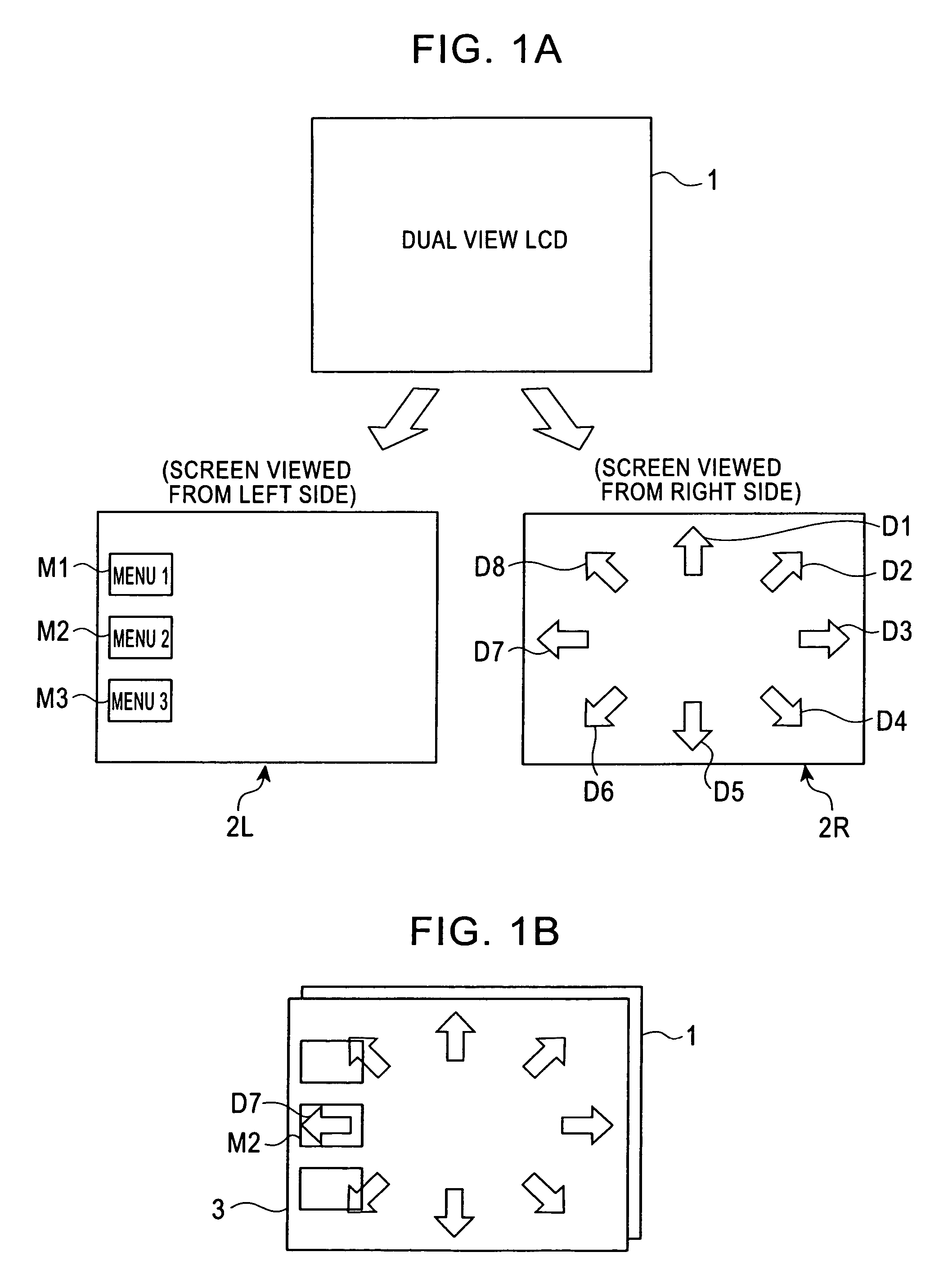
However, when a currently-available touch panel (i.e., an interface that allows input operation, upon the touch of an operation button, icon, or the like displayed on the screen) is provided on the dual-view LCD, an inconvenience occurs when in use.
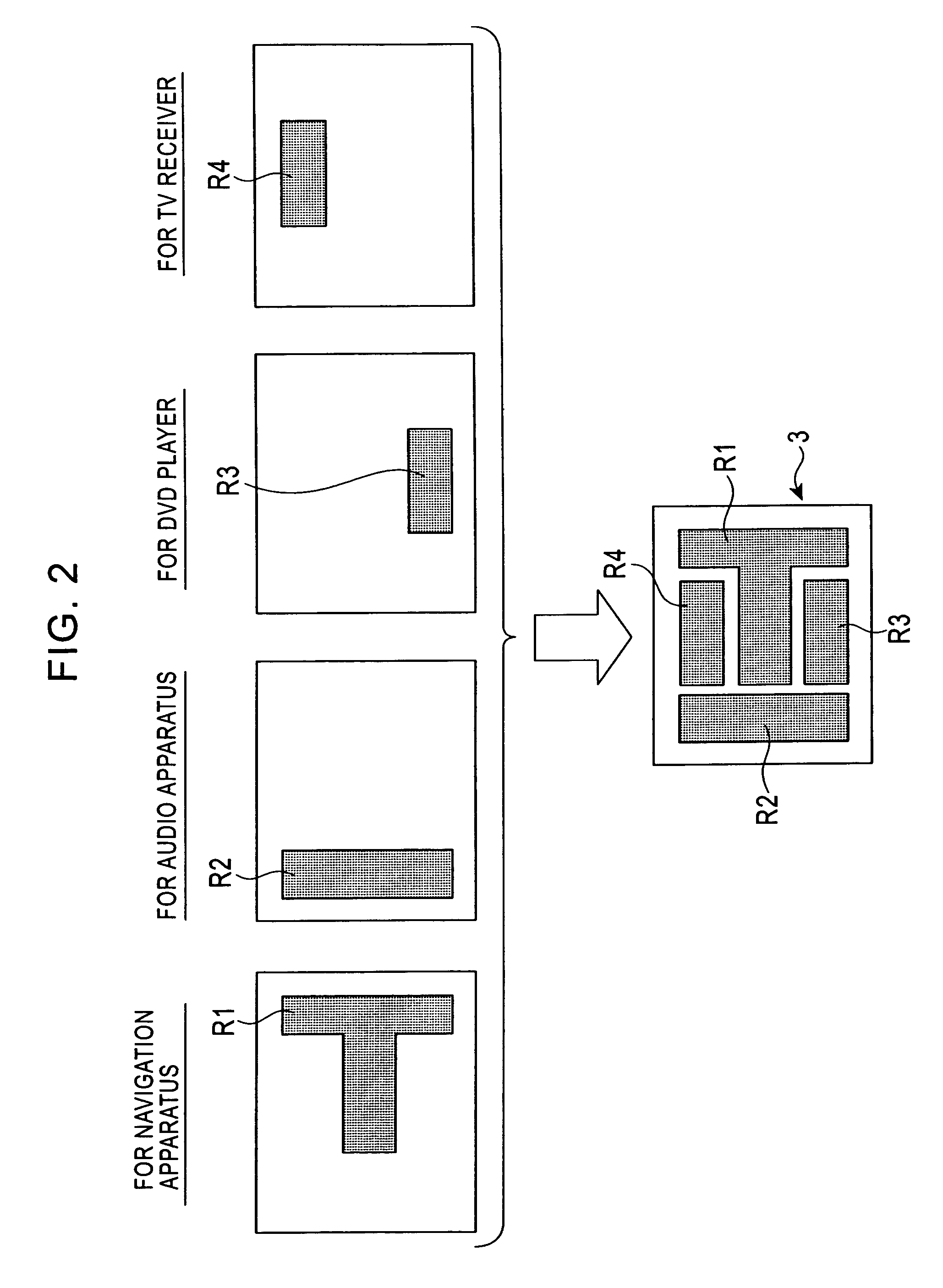
However, when the number of sources increases, inconvenience arises.
Specifically, the layout freedom is restricted, the screen design is restricted, and the external appearance is also impaired.
That is, there is a problem in that the inconvenience illustrated in FIG. 1B arises, unless the operation buttons are laid out with care.

Method used


Image

  • Display control system, operation input apparatus, and display control method
  • Display control system, operation input apparatus, and display control method
  • Display control system, operation input apparatus, and display control method

Examples


Embodiment Construction

[0025]An embodiment of the present invention will be described below with reference to the accompanying drawings.

[0026]FIG. 3 is a block diagram schematically showing the configuration of a system in which a display control system according to an embodiment of the present invention is applied to a vehicle.

[0027]A vehicle-mounted display control system 10 according to the present embodiment includes a dual-view LCD (liquid crystal display / panel) 11, a touch panel 12 disposed on the screen of the LCD 11, a touch-position detector 13, an identification-signal detector 14, a controlling unit 15 for controlling the entire system, a memory unit 16, and various sources (a television receiver 17, a navigation apparatus 18, and a DVD player 19 in the illustrated example). The display control system 10 further includes an LCD driver 20, signal generators 31a and 31b for generating signals (identification signals) S1 and S2 having frequencies f1 and f2 different from each other, and conductive...


PUM


Abstract

A system includes a display, a touch panel, a controlling unit, and an LCD driver. The display can display, on a screen, different images when viewed from different sides. The touch panel is disposed on the screen. The controlling unit and the LCD driver cooperate to control the display. In one embodiment, identification signals for uniquely identifying the different sides are generated and are electrically applied to respective operators. A component of the identification signal transmitted through the body of the operator is detected to thereby identify from which side operation input was performed on the touch panel.

Description

BACKGROUND[0001]1. Field of the Invention[0002]The present invention relates to display control systems. More specifically, the present invention relates to a technology useful for displaying appropriate images corresponding to the left and right sides on the screen of a display unit (e.g., a vehicle-mounted display apparatus) having a configuration in which a touch panel is provided on a liquid crystal display (hereinafter also referred to as a “dual-view LCD”), which can display different images when the same screen is viewed from the left side and the right side.[0003]2. Description of the Related Art[0004]Typically, LCDs (liquid crystal displays) are used as vehicle-mounted display apparatuses. Such a vehicle-mounted LCD is typically installed at the approximate center position of the center console in the vehicle cabin so that the screen can be viewed from both the driver seat and the front passenger seat. In known vehicle-mounted LCDs, a single LCD is used for displaying both ...

Claims


Application Information

Patent Timeline
Patent Type & Authority Patents(United States)
IPC IPC(8): G06F3/041G06F3/048G06F3/0487G06F3/0488
CPCH04N13/0404G06F3/0416G06F3/041H04N13/305G06F3/0488G06F3/042G06F3/0425G06F2203/04101G06F3/04186G06F3/044
Inventor KAWABE, HISASHI
Owner ALPINE ELECTRONICS INC
Learn More