Tuned liquid damper

a liquid damper and tuning technology, applied in vibration dampers, building components, sustainable buildings, etc., can solve the problems of large angular changes, and rectangular and cylindrical tuned liquid dampers that do not work well for rotational vibration. , to achieve the effect of improving performance to mass ratio, large angular changes, and high participation factor

Inactive Publication Date: 2011-07-05
DANMARKS TEKNISKE UNIV
View PDF16 Cites 9 Cited by
  • Summary
  • Abstract
  • Description
  • Claims
  • Application Information

AI Technical Summary

Benefits of technology

[0011]A second aspect of the current invention is to provide a tuned liquid damper as mentioned in the opening paragraph which can tolerate large angular changes.
[0012]A third aspect of the current invention is to provide a tuned liquid damper as mentioned in the opening paragraph which can dampen both rotational and translational vibrations.
[0013]The above mentioned aspects are solved in part by a tuned liquid damper as mentioned in the opening paragraph where the inner surface of the hollow cavity is essentially spherical. In this way, a tuned liquid damper is provided which has a higher mass participation factor which means that the performance to mass ratio is improved. Furthermore, the provided tuned liquid damper has a response which is independent of the orientation of the tuned liquid damper. The provided tuned liquid damper can also be used to dampen both rotational and translations motions.
[0014]In a preferred embodiment, the tuned liquid damper could further comprise first fluid damping means arranged within the essentially spherical cavity of the housing. In this way, the damping of the damper can be increased. The first fluid damping means could furthermore be self aligning. In this way, the damping action is constant and independent of the orientation of the tuned liquid damper.
[0016]In another preferred embodiment of a tuned liquid damper the tuned liquid damper could further comprise an inner element with an essentially spherical outer surface, where the inner element could be arranged essentially co-centric within the essentially spherical hollow cavity of the housing and could be essentially rigidly connected to the housing. In this way, a damper is provided which could have an even higher mass participation factor.
[0020]In another embodiment of the tuned liquid damper according to the current invention the fluid used could be an electro or a magnetic rheological fluid. In another embodiment, the fluid could be a thixopropic fluid. Using fluids of these types increases the possibilities for control of the TLD.

Problems solved by technology

The rectangular and cylindrical liquid dampers are therefore quite heavy since a large amount of liquid is required to obtain the desired damping effect.
Furthermore, the rectangular and cylindrical tuned liquid dampers do not work well for rotational vibrations.
In addition, rectangular and cylinder TLDs do not work in situations where the TLD is exposed to large angular motions or in cases where proper alignment of the TLD is difficult to achieve.
However, it has not been possible to find other references showing the use of liquid slosh dampers with spherical housings.

Method used


Image

  • Tuned liquid damper
  • Tuned liquid damper
  • Tuned liquid damper

Examples


embodiment 1

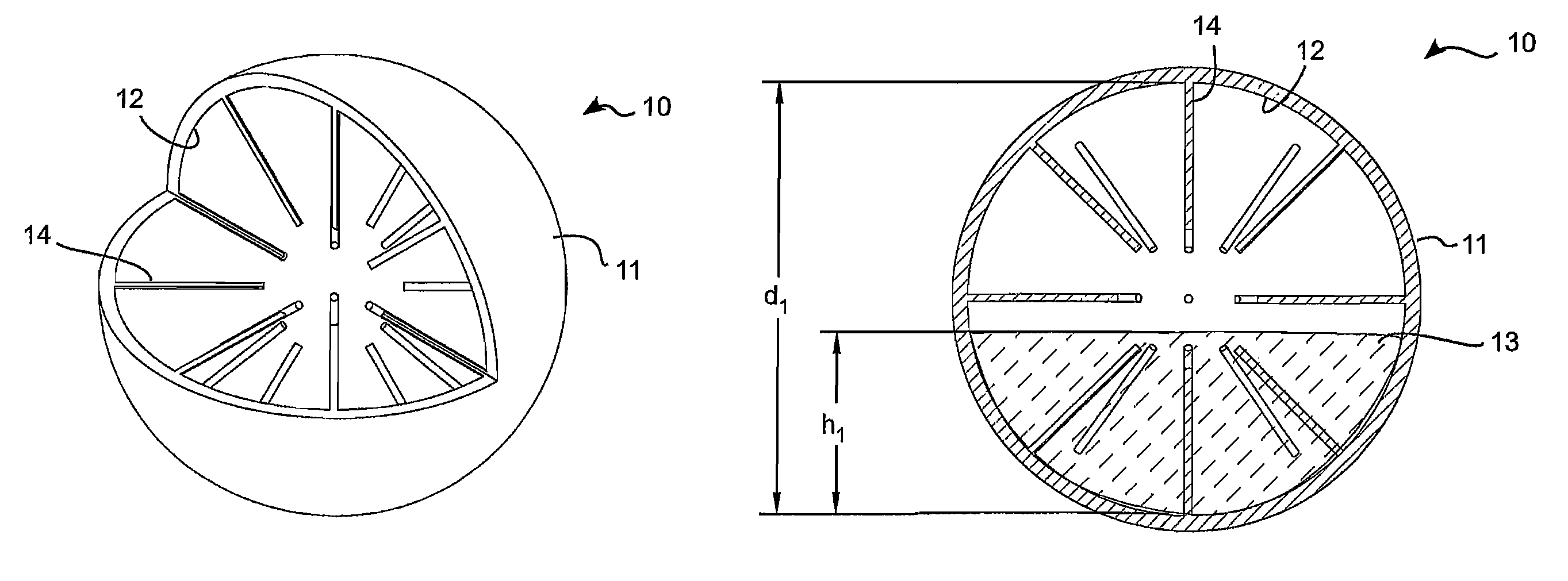
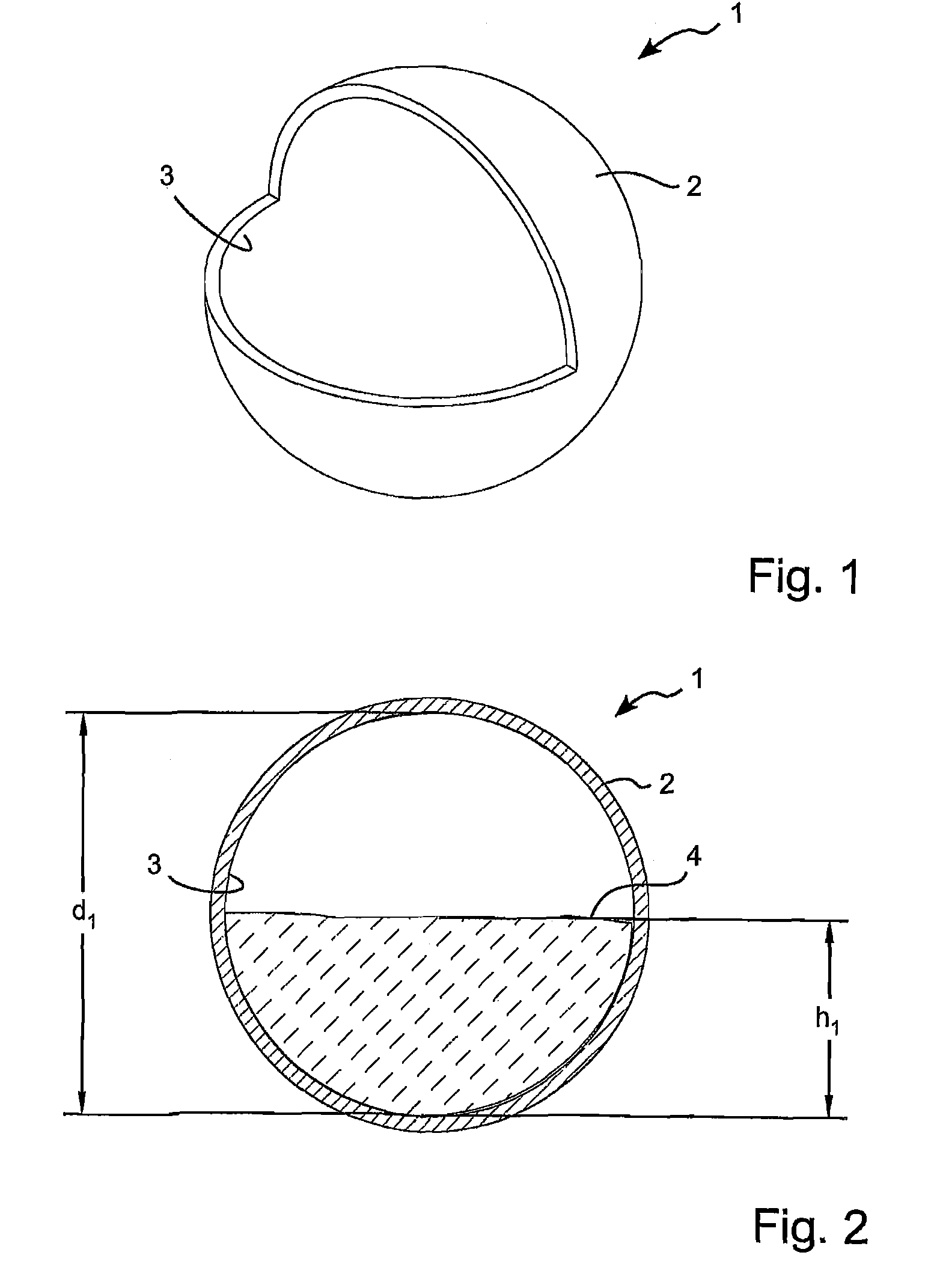
[0040]FIGS. 1 and 2 show a first and simple embodiment 1 of a spherical tuned liquid damper (STLD) according to the invention. The STLD 1 comprises a spherical housing 2 and a hollow inner cavity 3 inside the housing 2. The inner surface of the hollow inner cavity 3 is spherical with a diameter of “d1”. The hollow inner cavity 3 is partially filled with a fluid 4. The amount of fluid 4 in the hollow inner cavity 3 is defined by the height “h1” of the liquid. When the STLD 1 is displaced, the liquid will slosh back and forth within the inner cavity 3. However, it should be noted that from experimental tests, it can be seen that at around the dominant frequency of the STLD, the motion of the fluid in the STLD becomes circular. The sloshing effect of the fluid therefore reduces around the dominant frequency of the STLD.

[0041]The natural frequency of the STLD is a function of the diameter d1 of the inner cavity 3 and the height h1 of the fluid. It is to be noted that while a few authors...

embodiment 40

[0066]Furthermore, in the current embodiment 40, the inner element 44 has a spherical inner cavity 46 of diameter d2 partially filed with a second fluid 47 having a height h2. The natural frequency of the first fluid 43 and the second fluid 47 can be chosen different from each other. In one example, the natural frequency of the first fluid 43 could be chosen to match the frequency of the first mode of the structure to be dampened and the natural frequency of the second fluid 47 could be chosen to match the frequency of the second mode of the structure to be dampened. In this way, the frequencies of both the first and second modes of the structure can be dampened.

[0067]It is to be noted, that in order to achieve the higher mass participation of the sphere in sphere embodiment, it is not necessary for the inner element to have an inner cavity filed with a second fluid. The inner element could be solid or filled with air. In this case, the STLD will have only a single natural frequency...

embodiment 60

[0070]The embodiment 60 shown in FIGS. 14-16, is an example of a housing 61 in the form of a partial sphere where another smaller partial sphere 62 is arranged inside the first partial sphere. The inner partial sphere 62 is held in place by support elements 63 arranged between the inner partial sphere 62 and the outer partial sphere 61. This arrangement results in a gap 64 between the two partial spheres 61,62. The effect of this is to further increase the mass participation of the fluid 65 arranged in the gap. This embodiment is suitable for applications where a low frequency is desired.


PUM


Abstract

A tuned liquid damper comprising a housing with a hollow cavity within said housing and a first fluid which partially fills said hollow cavity. The inner surface of said hollow cavity is essentially spherical. The tuned liquid damper further comprises first fluid damping means arranged within the essentially spherical cavity of the housing. In this way, a tuned liquid damper is provided which has a response which is constant and independent of the orientation of the tuned liquid damper. Damping means are provided in order to be able to control the damping effect of the tuned liquid damper.

Description

CROSS REFERENCE TO PRIOR APPLICATIONS[0001]This application is the U.S. national phase of International Application No. PCT / DK2007 / 000075, filed Feb. 15, 2007, which claims priority from U.S. Provisional Application No. 60 / 774,064, filed Feb. 15, 2006 and European Application No. 06388008.2, filed Feb. 15, 2006. Each application is incorporated herein by reference in their entirety. The International Application was published in English on Aug. 23, 2007 as WO 2007 / 093180 under PCT Article 21(2).[0002]The current invention relates to a tuned liquid damper. The tuned liquid damper of the current invention comprises a housing with a hollow cavity arranged within the housing and a fluid which at least partially fills said hollow cavity.[0003]A tuned liquid damper (TLD) is a kind of passive mechanical damper apparatus that relies upon the motion of a fluid in a tank for changing the dynamic characteristics of the structure to which it is attached. In addition, a tuned liquid damper dissi...

Claims


Application Information

Patent Timeline
Patent Type & Authority Patents(United States)
IPC IPC(8): E04H9/02F16F9/10F16F9/00
CPCE04B1/985F16F7/10E04H2009/026Y02B10/30E04H9/0215E04H9/0235
Inventor GEORGAKIS, CHRISTOS T.
Owner DANMARKS TEKNISKE UNIV
Why Eureka
Try Eureka