
Coned disc spring

a coned disc spring and disc spring technology, applied in the direction of ring springs, interengaging clutches, shock absorbers, etc., can solve the problems of large reduction of the durability of the coned disc spring b>300/b>, wear on the inside of the clutch drum, etc., to reduce the stress occurring, reduce the wear of the spline groove caused by the tooth, and reduce the stress occurring.

Inactive Publication Date: 2011-07-05
NHK SPRING CO LTD
View PDF15 Cites 3 Cited by
  • Summary
  • Abstract
  • Description
  • Claims
  • Application Information

AI Technical Summary

Benefits of technology

The stress relaxation portion effectively reduces stress at the tooth base during clutch engagement, decreases wear on spline grooves, and improves the durability of the coned disc spring, ensuring reliable operation for increasing automobile mileage.

Problems solved by technology

Therefore, the coned disc spring 200 frequently hits the inside wall of the clutch drum 101, which may cause a problem of wear on the inside of the wall of the clutch drum 101.
Therefore, there has been a problem in that the durability of the coned disc spring 300 is greatly decreased.

Method used


Image

  • Coned disc spring
  • Coned disc spring
  • Coned disc spring

Examples


Embodiment Construction

1. Compositions of Embodiment

A. Coned Disc Spring

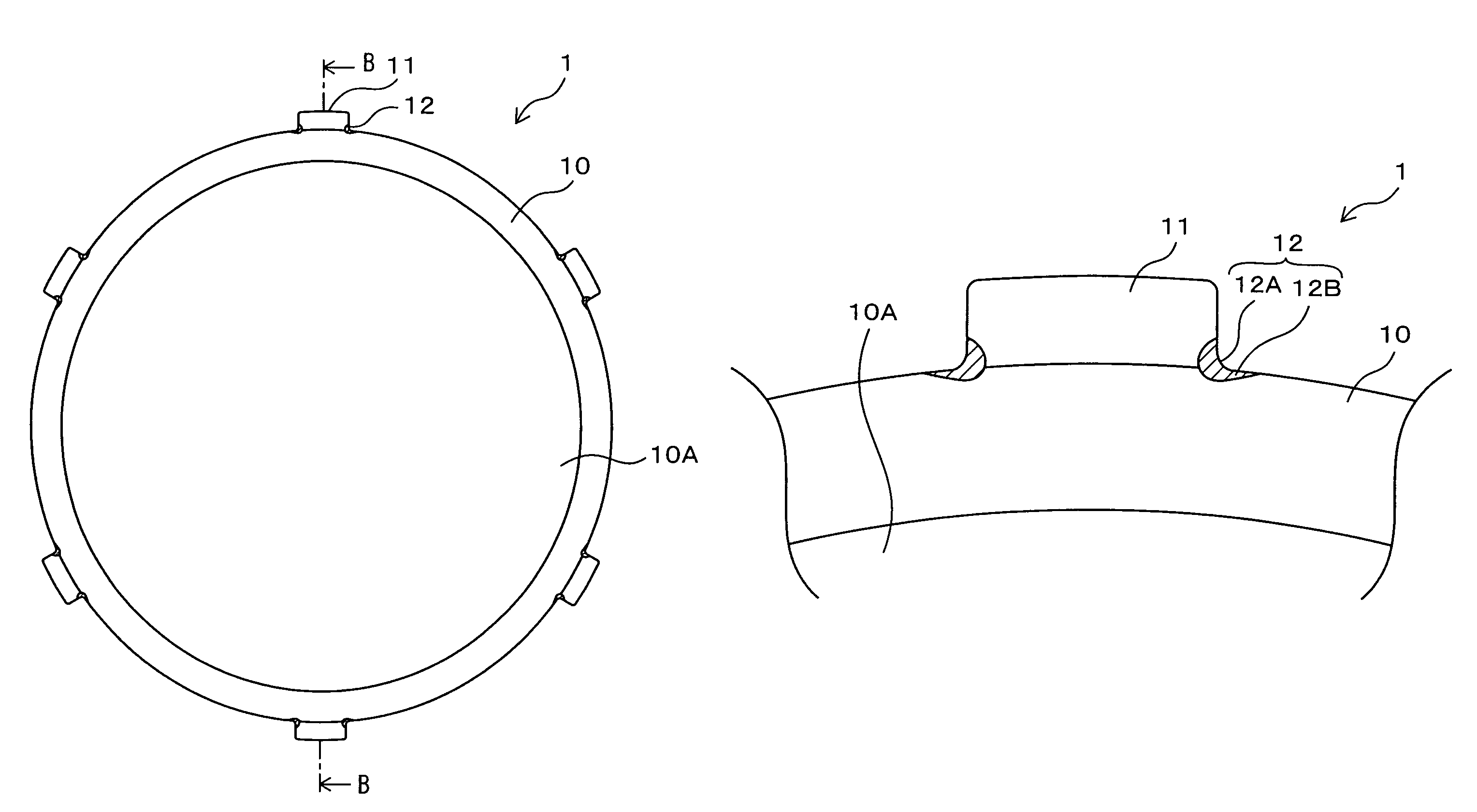
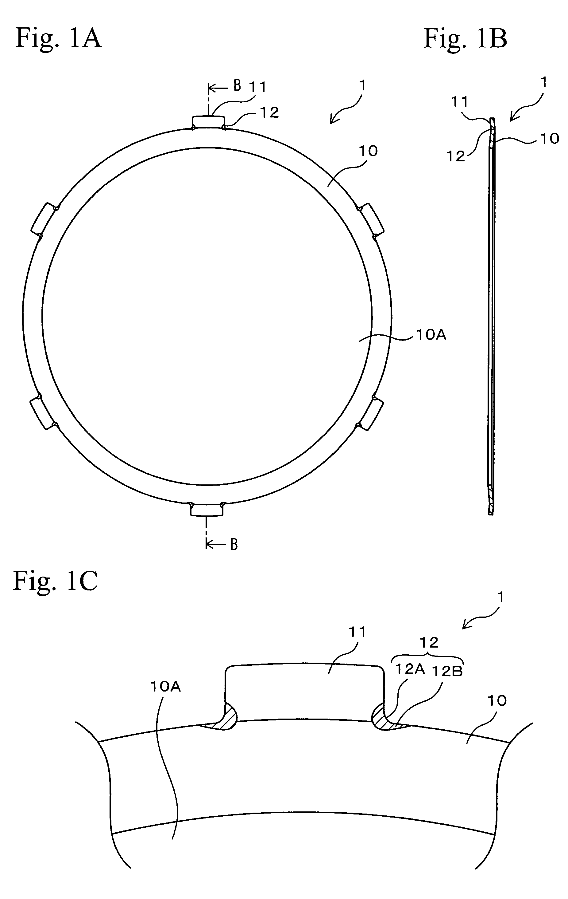
An embodiment of the present invention is explained with reference to the drawings. FIGS. 1A to 1C are views showing a composition of a coned disc spring 1 relating to a first embodiment of the present invention, and FIG. 1A is a plan view, FIG. 1B is a sectional side view taken along line B-B of FIG. 1A, and FIG. 1C is a partially enlarged view of FIG. 1A. The coned disc spring 1 comprises a body 10 having a circular dish shape and has a hole 10A having a circular shape in the center of the body 10. The outer periphery of the body 10 is formed with plural teeth 11 (for example, six teeth) at equal intervals along the circumferential direction. The teeth 11 have an approximately rectangular shape and project to the radial outer side of the body 10.

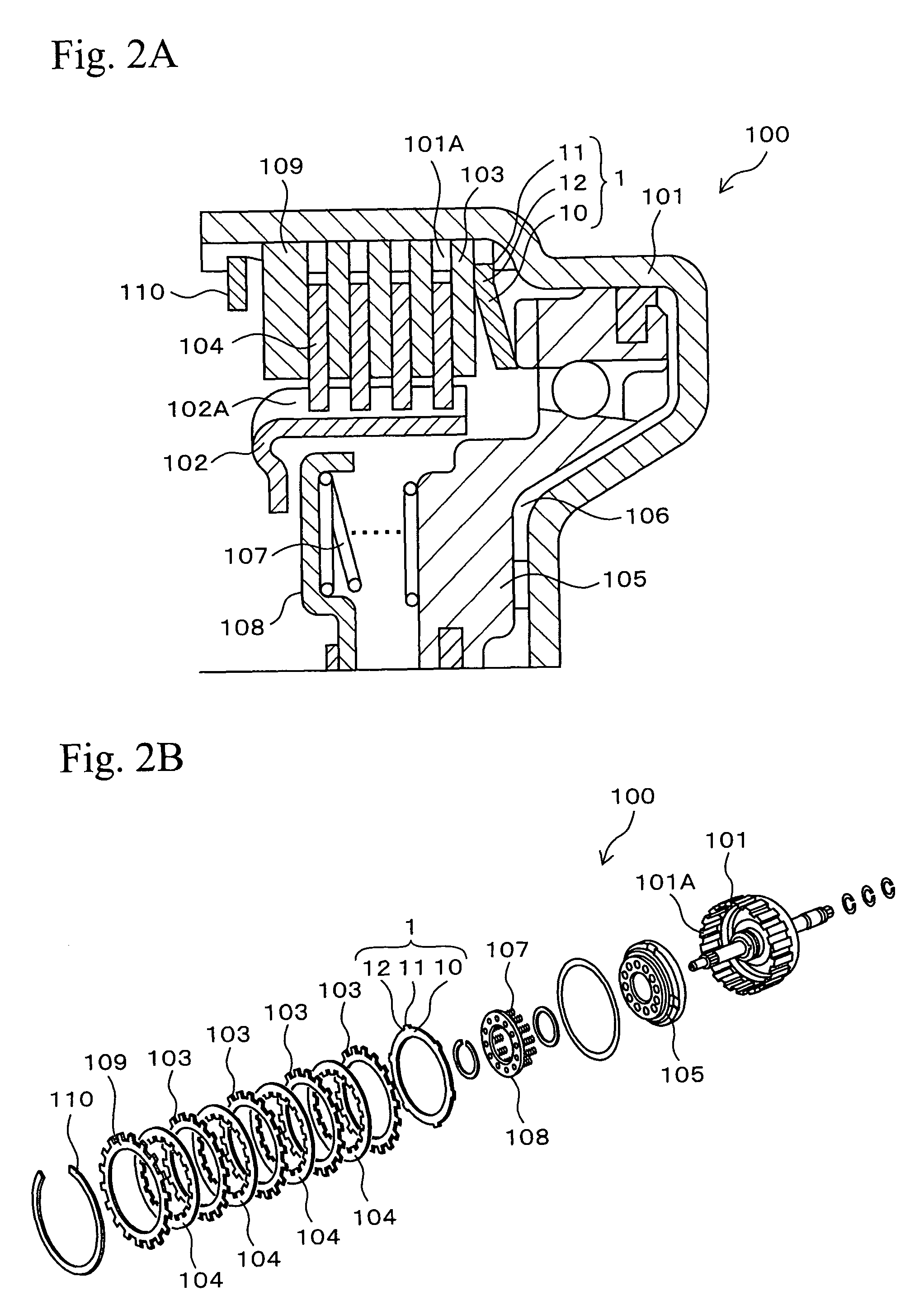
For example, when the teeth 11 are applied to the following clutch structure 100, they may prevent the coned disc spring 1 from relative rotating with respect to a clutch drum 101. It should...


PUM


Abstract

A coned disc spring is arranged between a second component and a third component provided inside a tubular first component and movable in an axial direction. The coned disc spring comprises a body having a circular dish shape, teeth closely fitting into spline grooves formed on an inner peripheral surface of the first component and projecting to a radial outer side on an outer periphery of the body, and a stress relaxation portion formed in a flat shape or a curved shape at an edge portion of a circular arc portion at the base of the tooth in a direction at least one of a circumferential direction and a radial direction of the body.

Description

TECHNICAL FIELDThe present invention relates to coned disc springs that are used to absorb shocks occurring during the engaging of a clutch of a multiplate clutch structure of a transporting machine. Specifically, the present invention relates to improvement in a coned disc spring comprising teeth for inhibiting relative rotation with respect to a clutch drum.BACKGROUND ARTA wet-type multiplate clutch structure is used as a clutch structure in a transmission of a transporting machine. The wet-type multiplate clutch structure comprises a coned disc spring used for absorbing shocks occurring during the engaging of a clutch. FIG. 3 is an enlarged sectional side view showing a composition of a multiplate clutch structure 100 provided with a conventional coned disc spring 200. The multiplate clutch structure 100 comprises a cylindrical clutch drum 101 having a bottom. Plural spline grooves 101A extending in the axial direction are formed on the inner peripheral surface of the clutch drum...

Claims


Application Information

Patent Timeline
Patent Type & Authority Patents(United States)
IPC IPC(8): B60T13/04
CPCF16D13/583F16D25/0638
Inventor IMAIZUMI, HIRONOBU
Owner NHK SPRING CO LTD
Learn More