Liquid dispenser device

Inactive Publication Date: 2011-07-05
APTAR FRANCE SAS
View PDF12 Cites 0 Cited by
  • Summary
  • Abstract
  • Description
  • Claims
  • Application Information

AI Technical Summary

Benefits of technology

[0008]In another aspect of the invention, the pusher comprises a bearing plate on which a user can exert pressure by means of a finger, and a peripheral skirt forming the dispenser orifice, the deformable wall being formed in the plate, advantageously by reducing the wall thickness of the plate. The skirt advantageously comes into abutment against the body in the depressed position, the deformable wall thus deforming so as to displace the piston and thus open the outlet valve. The piston is advantageously in contact with the wall in the depressed position. The deformable wall advantageously presents resistance to deformation that is greater than the force exerted by the spring, and greater than or equal to the maximum pressure existing in the chamber. The wall advantageously deforms after the pusher has reached its depressed position.

Problems solved by technology

Thereafter, the forces experienced by the pump during its normal operation are not sufficient to cause the wall to deform.
However, in normal conditions of use, the wall remains static.

Method used


Image

  • Liquid dispenser device
  • Liquid dispenser device

Examples


Embodiment Construction

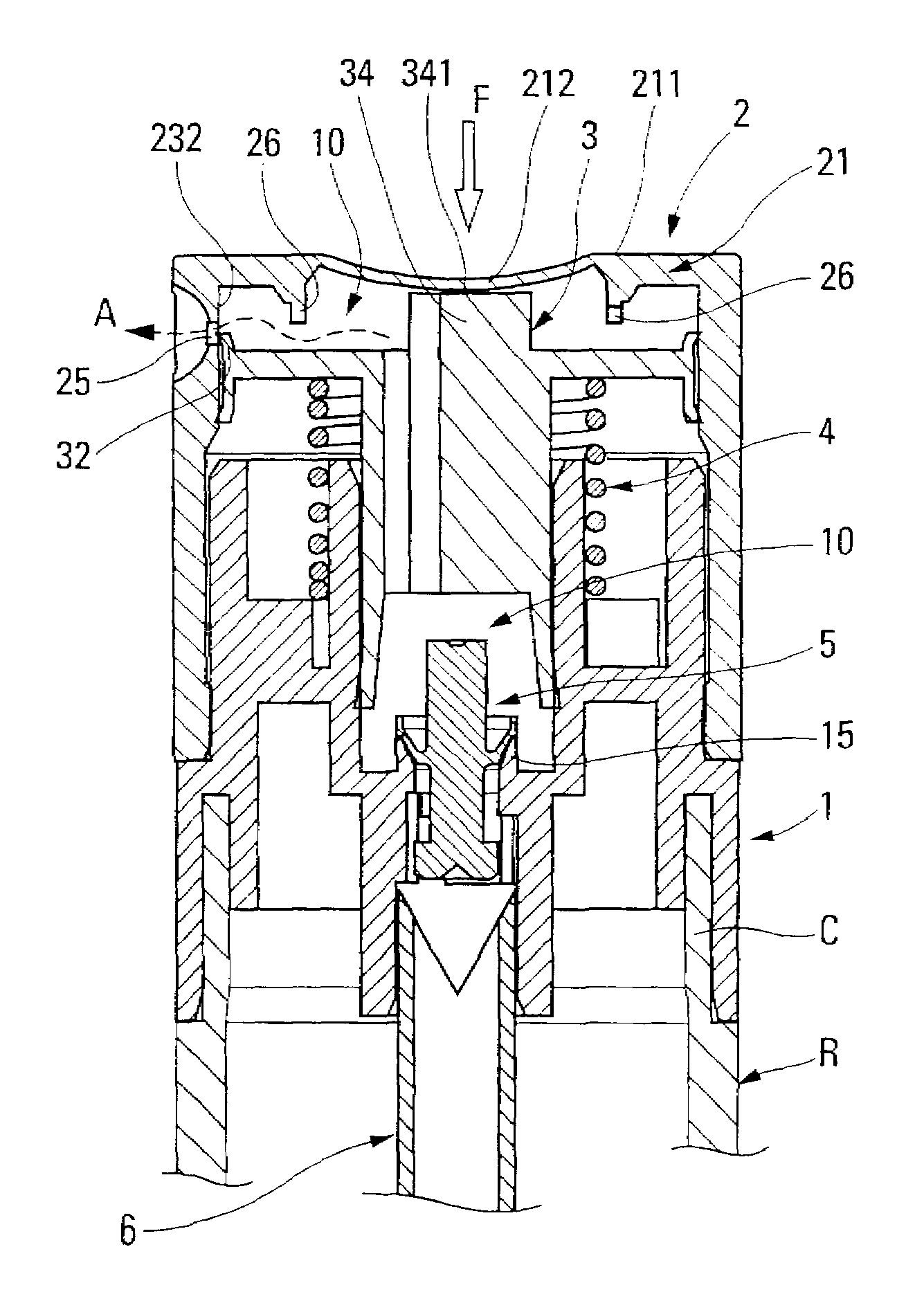
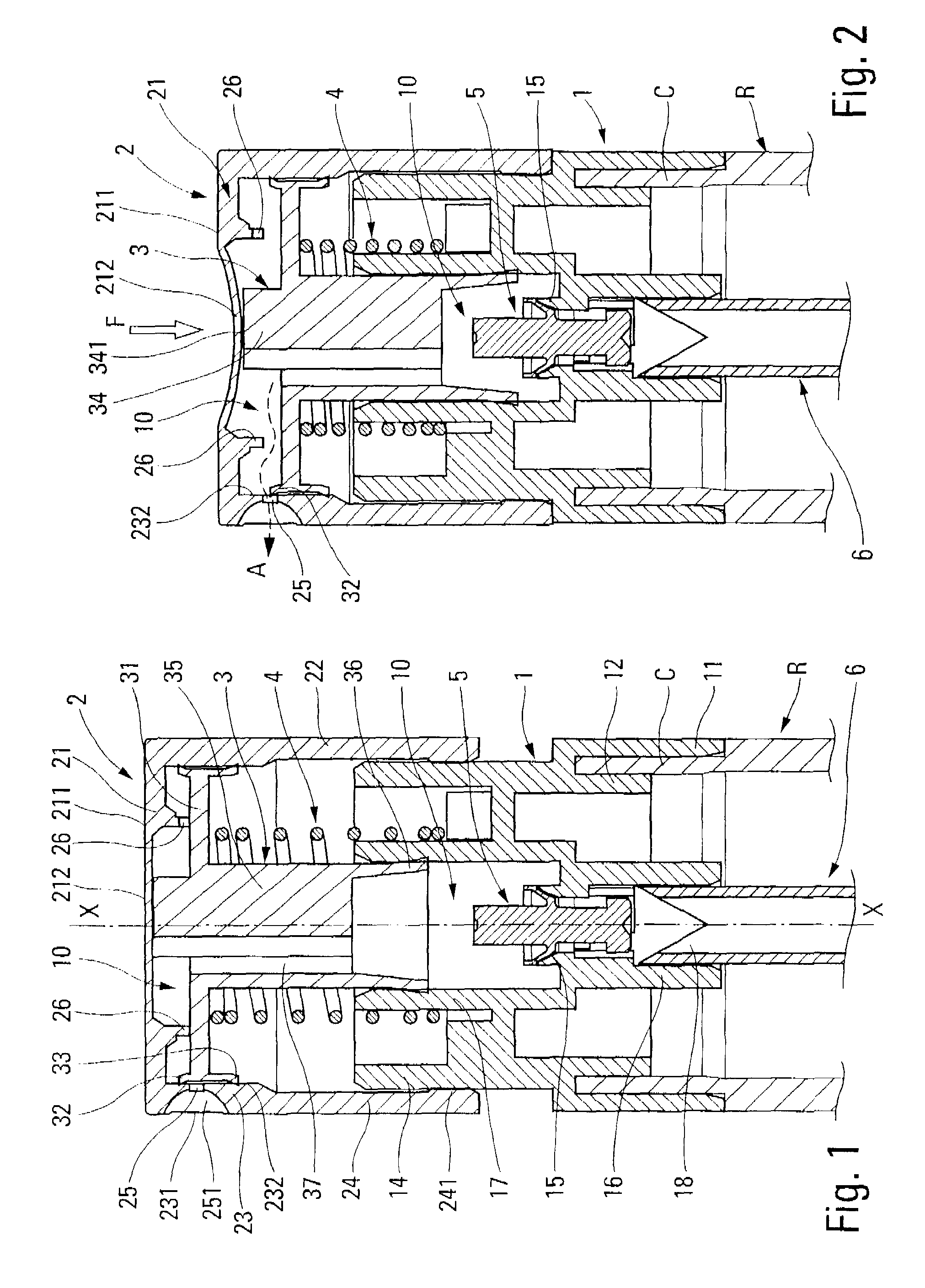
[0014]The dispenser device of the figures is a pump that is shown associated with a receptacle R including a neck C on which the dispenser device of the invention is fastened.

[0015]The pump comprises five component elements, namely a body 1, a pusher 2, a piston 3, a spring 4, and an inlet valve member 5 The pump can further comprise a dip tube 6. The body, the pusher, the piston, the valve member 5, and the dip tube 6 are preferably made by molding a plastics material. The pump includes a pump chamber 10.

[0016]The body 1 includes a fastener ring 11 that co-operates with the neck C, so as to fasten the pump on the receptacle R. The ring 11 is engaged with the outside of the neck. In addition, the body forms a self-sealing lip 12 that is in leaktight engagement with the inside wall of the neck. The body 1 also forms a guide bushing 14. The body also forms a main piston-receiving cylinder 17 that internally defines a leaktight sliding surface having a function that is explained below....


PUM


Abstract

A liquid dispenser device for being associated with a liquid reservoir (R), said device comprising:a chamber (10) provided with an inlet valve (5, 15), an outlet valve (32, 232), and a piston (3) that is suitable for varying the volume of the chamber;a liquid dispenser orifice (25); anda pusher (2) that is axially displaceable down and up between a rest position and a depressed position;the dispenser device being characterized in that the pusher (2) includes an elastically-deformable wall (212) that is thus displaceable relative to the remainder of the pusher, the piston (3) being in contact, at least momentarily, with the deformable wall (212), so as to be urged in displacement relative to the remainder of the pusher while the wall is being deformed, in such a manner as to open the outlet valve.

Description

CROSS REFERENCE TO RELATED APPLICATION[0001]This application claims the benefit under 35 U.S.C. §119(e) of pending U.S. provisional patent application Ser. No. 60 / 871,584, filed Dec. 22, 2006, and priority under 35 U.S.C. §119(a)-(d) of French patent application No. FR-06.53964, filed Sep. 27, 2006.TECHNICAL FIELD[0002]The present invention relates to a liquid dispenser pump that is generally associated with a liquid reservoir, which together constitute a liquid dispenser. It relates to a dispenser member that is generally actuated manually by means of a finger of the user. The liquid is dispensed in the form of a jet of fine spray droplets, a continuous stream, or even a knob of liquid, particularly for viscous liquids, such as cosmetic creams. Such a liquid dispenser member can be used in particular in the fields of perfumery, cosmetics, or even pharmacy for dispensing liquids that are viscous to a greater or lesser extent.BACKGROUND OF THE INVENTION[0003]The present invention rel...

Claims


Application Information

Patent Timeline
IPC IPC(8): B65D88/54
CPCB05B11/304B05B11/3061B05B11/3069B05B11/3074B05B11/3022B05B11/1022B05B11/104B05B11/1061B05B11/1069B05B11/1074
Inventor DUQUET, FREDERICLECOUTRE, JEAN-PAUL
Owner APTAR FRANCE SAS
Why Eureka
Try Eureka