
Independent suspension assembly

a technology of independent suspension and front suspension, which is applied in the direction of resilient suspension, vehicle springs, vehicle components, etc., can solve the problems of difficult incorporation of independent front suspension systems into large trucks, and undesirable suspension characteristics of suspension systems having rigid axles extending across and between the front wheels of the vehicl

Active Publication Date: 2011-07-05
REYCO GRANNING
View PDF29 Cites 26 Cited by
  • Summary
  • Abstract
  • Description
  • Claims
  • Application Information

AI Technical Summary

Benefits of technology

"The present invention provides an improved independent suspension system for large trucks that allows for better handling and performance. The system includes a wheel support member, upper and lower control arms, and a linkage member. The system allows for vertical movement of the wheel support member and provides flexibility in wheel support and load transfer. The invention also includes a leaf spring assembly and an air spring assembly for load transfer. The system can be used with steerable wheels and is particularly useful for vehicles with a longitudinal centerline. The lower control arms extend below the engine of the vehicle and are pivotally secured to the frame. The technical effects of the invention include improved vehicle handling, performance, and flexibility in wheel support and load transfer."

Problems solved by technology

The suspension characteristics of suspension systems having a rigid axle extending across and between the front wheels of the vehicle are generally undesirable because a bump experienced by one of the front wheels causes the entire front axle and, thus, the vehicle to move in response to the bump.
The incorporation of independent front suspension systems in a large truck, however, is difficult.
A primary source of this difficulty is that the engines of such large trucks often extend between and below the truck chassis frame members into the same space where independent front suspension components are typically located.

Method used


Image

  • Independent suspension assembly
  • Independent suspension assembly
  • Independent suspension assembly

Examples


Embodiment Construction

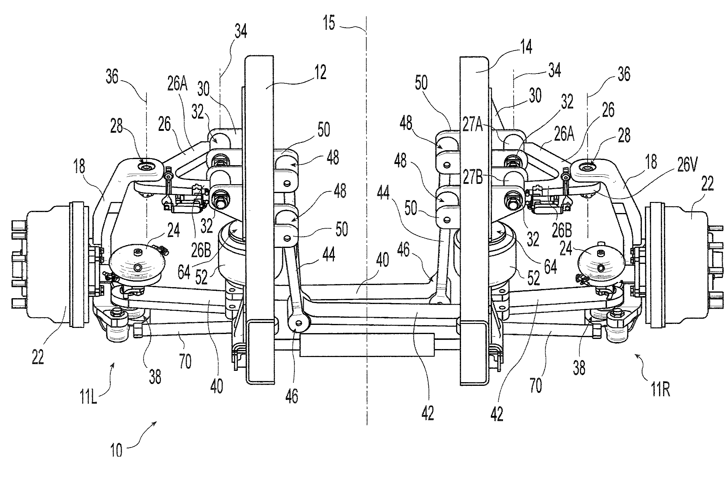
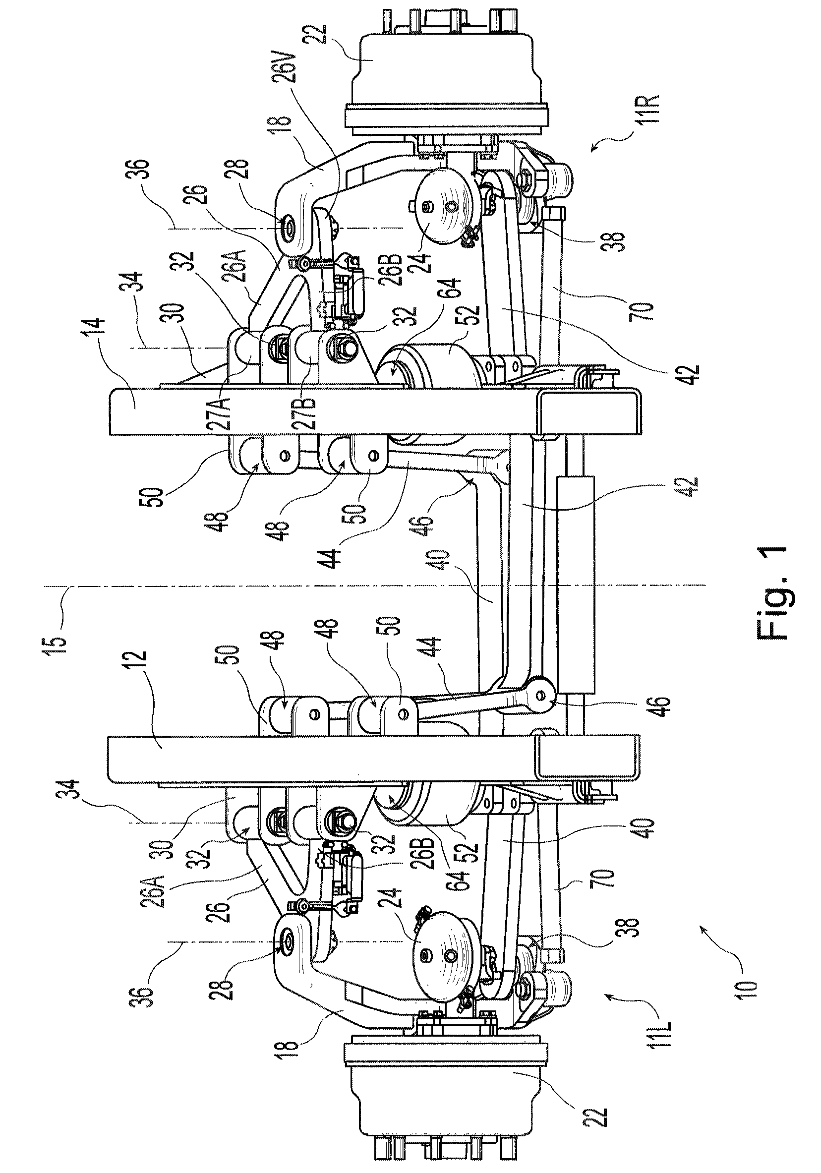
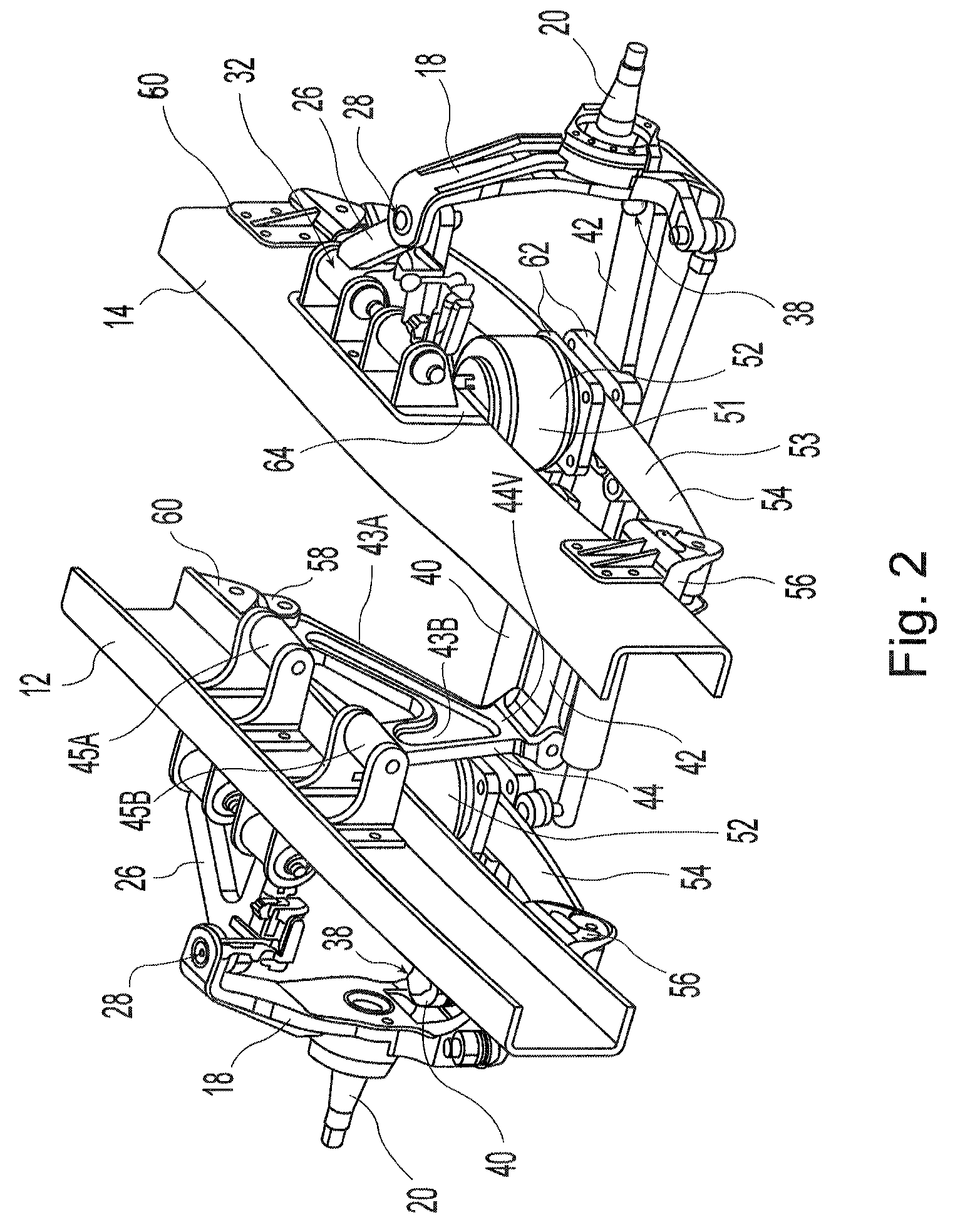
[0023]An independent front suspension system constructed in accordance with the principles of the present invention is shown in the drawings and is generally indicated by the numeral 10. Independent suspension system 10 includes two separate independent suspension assemblies 11L, 11R for mounting a paired set of wheels of the vehicle. The two wheels mounted on the illustrated suspension assemblies 11L, 11R are the front steerable wheels of the vehicle and are located on opposite sides of the longitudinal centerline 15 of the vehicle. The illustrated independent suspension system 10 is adapted to be mounted on a truck or other vehicle chassis which includes a pair of longitudinally extending frame members 12 and 14 but may also be used with vehicles having alternative chassis configurations. Similarly, while the illustrated embodiment employs independent suspension assemblies 11L, 11R with the front, steerable wheels of the vehicle, similar independent suspension assemblies could als...


PUM


Abstract

An independent suspension assembly having a wheel support member and upper and lower control arms that is well adapted for use with the front steerable wheels of a large truck. The upper and lower control arms are each pivotally secured to the wheel support member at a first location on the control arm and pivotally supported relative to the frame at a second location on the control arm. The wheel support member is vertically displaceable relative to the frame by pivotal movement of the upper and lower control arms relative to both the frame and wheel support member. A leaf spring and an air spring may be positioned between the lower control arm and frame to communicate loads therebetween. A vertically extending linkage member may be disposed between the lower control arm and frame. The lower control arm may extend across the longitudinal centerline of the vehicle below the engine.

Description

CROSS REFERENCE TO RELATED APPLICATIONS[0001]This application claims priority under 35 U.S.C. 119(e) of U.S. provisional patent application Ser. No. 60 / 959,633 filed on Jul. 16, 2007 entitled INDEPENDENT FRONT SUSPENSION the disclosure of which is hereby incorporated herein by reference.BACKGROUND OF THE INVENTION[0002]1. Field of the Invention[0003]The present invention relates to independent suspension assemblies and, more particularly, to independent suspension assemblies that can be used with the steerable wheels of a vehicle.[0004]2. Description of the Related Art[0005]Steering suspensions for heavy duty trucks such as, for example, semi-tractor trucks, class 5 through 8 trucks, etc., are typically manufactured using a solid axle extending under the truck engine in a generally perpendicular or transverse to the longitudinal centerline of the truck. At each end of the rigid axle, spindles are typically pivotally attached with kingpins for thereby pivotally mounting the truck fro...

Claims


Application Information

Patent Timeline
Patent Type & Authority Patents(United States)
IPC IPC(8): B60G3/18B60G11/46
CPCB60G3/18B60G3/20B60G11/04B60G2200/144B60G2200/46B60G2202/112B60G2204/421
Inventor RICHARDSON, GREGORY A.
Owner REYCO GRANNING
Learn More