Inrush current limiter device and power factor control (PFC) circuit having an improved inrush current limiter device

Inactive Publication Date: 2011-07-05
KONINKLIJKE PHILIPS ELECTRONICS NV
View PDF11 Cites 7 Cited by
  • Summary
  • Abstract
  • Description
  • Claims
  • Application Information

AI Technical Summary

Benefits of technology

[0008]Therefore, it is an object of the present invention to provide a power factor control circuit having an IGBT-based switch suitable for realizing smooth slopes of current signals at the IGBT-based switch. Moreover, it is

Problems solved by technology

Unfortunately, the changes made to improve the efficiency of the ballast reduce certain external electrical resistances.
This gives rise to a new problem: the occurrence of a large inrush off-current upon the first application of electrical power.
For lighting circuit that contains a multiplicity of ballasts, the combined magnitude of the inrush is potentially large enough to cause contact failure of the switching device due to arching and contact welding.
While a NTC is only usable for lower power levels around a few hundred Watts due to its power losses, a relay has a low loss but a lifetime that is limited.
If t

Method used


Image

  • Inrush current limiter device and power factor control (PFC) circuit having an improved inrush current limiter device
  • Inrush current limiter device and power factor control (PFC) circuit having an improved inrush current limiter device
  • Inrush current limiter device and power factor control (PFC) circuit having an improved inrush current limiter device

Examples


Embodiment Construction

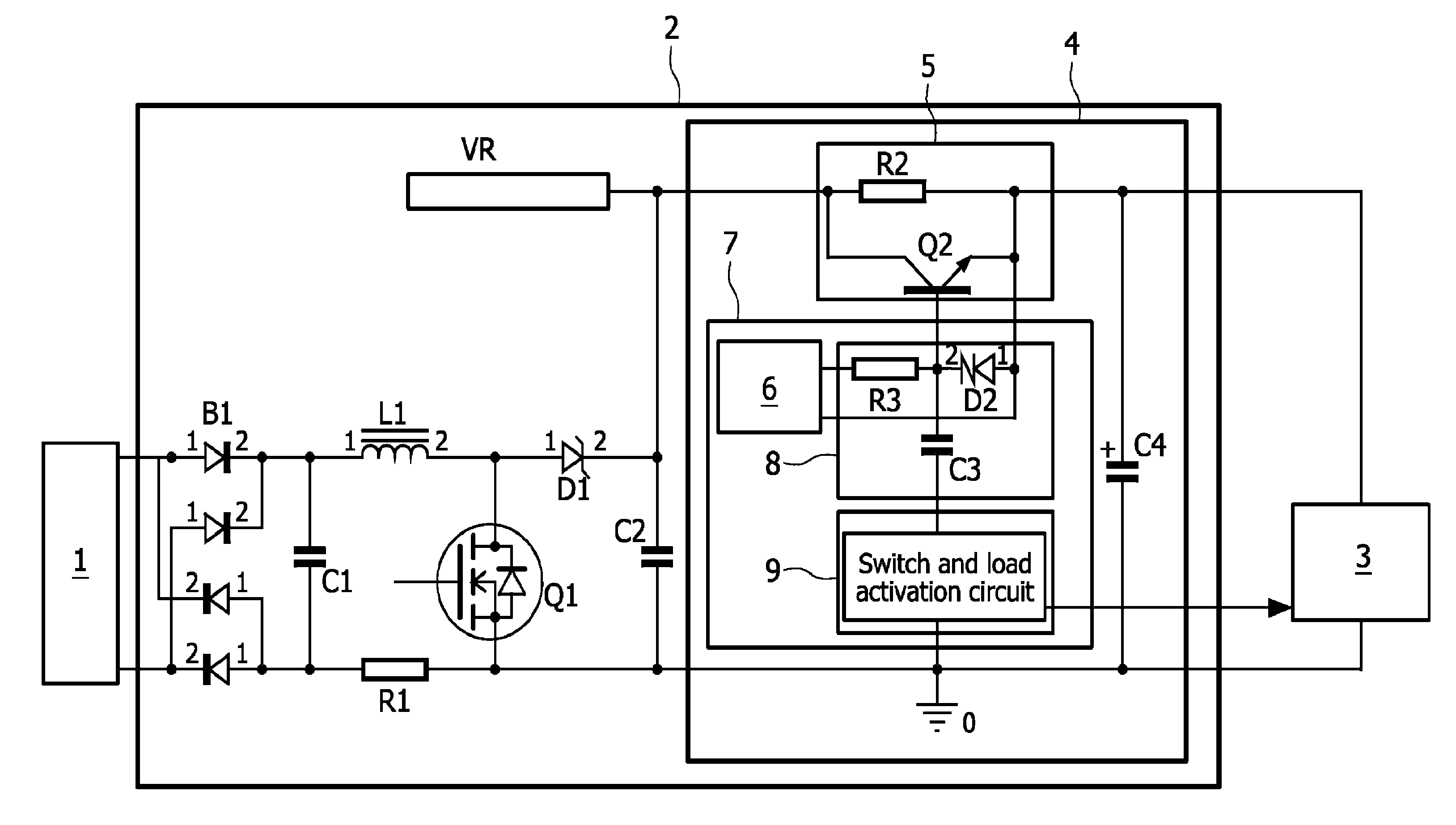
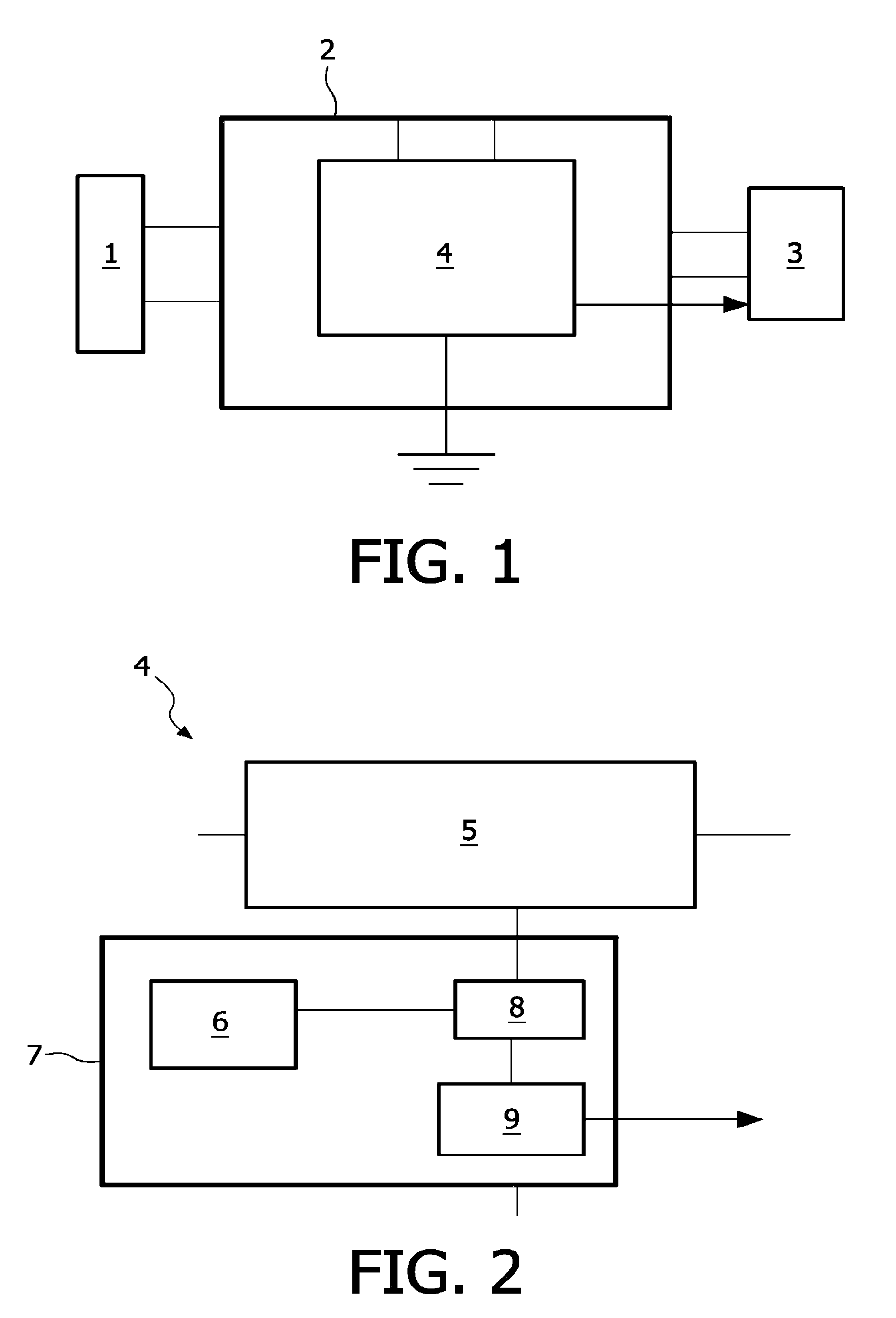
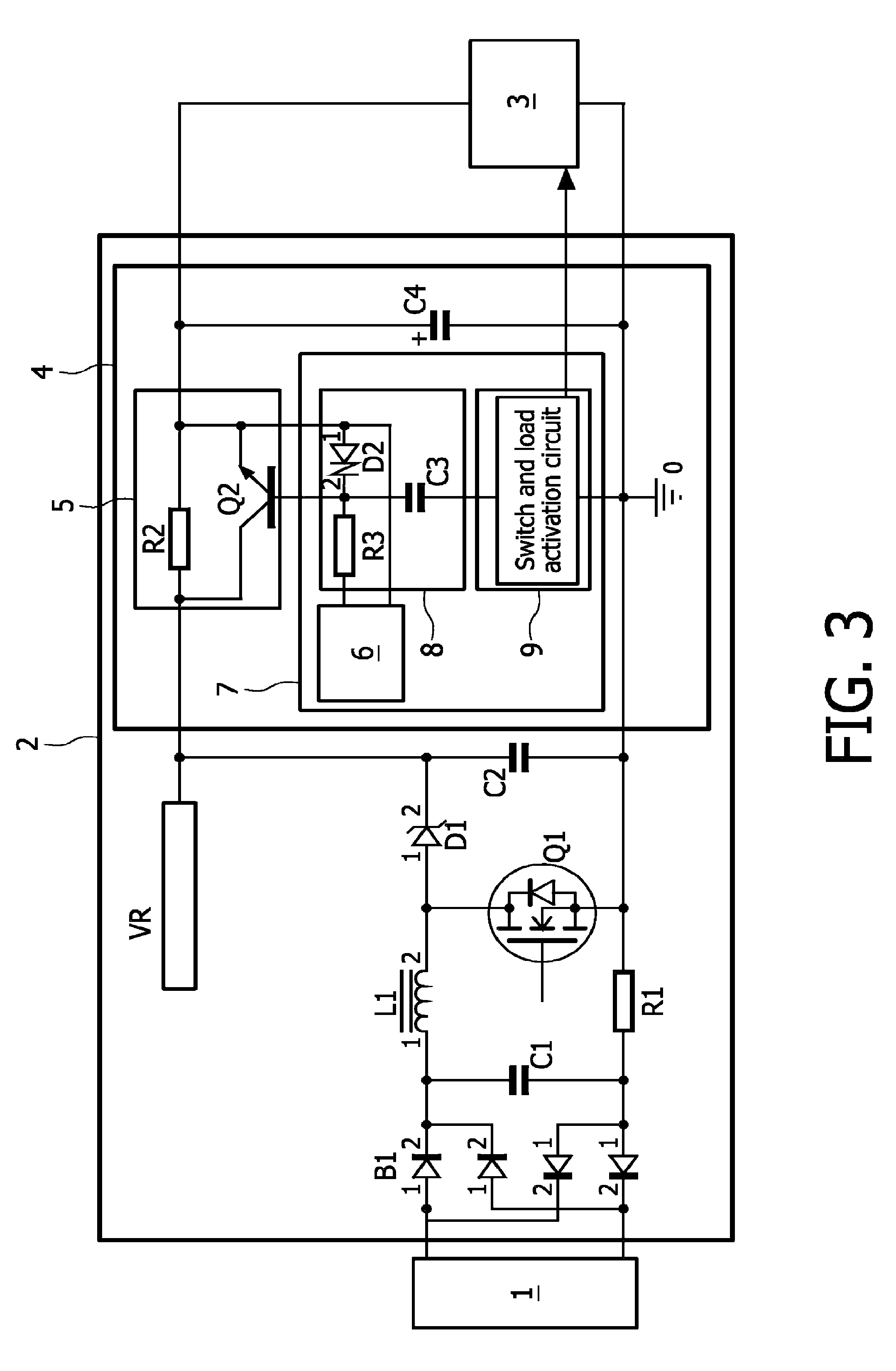
[0027]FIG. 1 shows schematically the design of the invention, whereby a mains fed 1 or a common ac source is connected to a PFC circuit 2 via leads. The PFC circuit 2 is connected to a load 3, whereby the load can be any load for example a lamp. The PFC-circuit further comprises an inrush current limiter device 4 which is at one end connected to ground and gets information from the load 3, represented by the arrow leaving the inrush current limiter device 4 in direction to the load 3. The inrush current limiter 4 is described in greater detail in FIG. 2.

[0028]FIG. 2 schematically shows the inventive inrush current limiter device 4. The inrush current limiter device 4 comprises an IGBT-based limiter unit 5 having a non limited and a limited conduction path (not shown in detail) which are alternatively coupled by a corresponding switch. The IGBT-based limited unit is supplied by an IGBT gate supply 6. The IGBT-based switch 5 is coupled to a control device 7 for controlling said IGBT-b...


PUM


Abstract

The present invention relates to an inrush current limiter device (4) for limiting inrushing current to a connectable load (3) comprising: at least one switchable IGBT-based limiter unit (5) for selectively limiting the inrushing current, having at least one current limiting conductor element for a limited leading of current and at least an IGBT-based switch (Q2), whereby the IGBT-based switch (Q2) is used as well as a controlled current limiter and as a by-pass element, and at least one control device (7) for controlling the IGBT-based switch (Q2), whereby the control device (7) comprises at least one IGBT-based switch supply (6) and means for realizing (8) a smooth flank of an output signal at the selected conductor element.

Description

BACKGROUND OF THE INVENTION[0001]The present invention relates to an inrush current limiter device for limiting inrushing current to a connectable load comprising: at least one switchable IGBT (Insulated Gate Bipolar Transistor)-based limiter unit for selectively limiting the inrushing current, having at least one current limiting conductor element for limited leading of current, and at least an IGBT-based switch, whereby the IGBT(Insulated Gate Bipolar Transistor)-based switch (Q2) is used as well as a controlled current limiter and as a by-pass element, and at least one control device for controlling the IGBT-based switch, whereby the control device comprises at least one IGBT-based switch supply and means for realizing a smooth flank of an output signal at the selected conductor element.[0002]The present invention further relates to a power factor control circuit connectable to and / or between a main fed and a load comprising: an AC / DC converter with a capacitive buffer unit, and ...

Claims


Application Information

Patent Timeline
IPC IPC(8): H02H9/00H02H9/08
CPCG05F1/70H02H9/001H02M1/42Y02B70/12Y02B70/10
Inventor SCHIENE, WOLFGANGGREUEL, GEORGBLEUKX, MARC MARIA ALEX
Owner KONINKLIJKE PHILIPS ELECTRONICS NV
Why Eureka
Try Eureka