Fault current limiter

a current limiter and fault technology, applied in the direction of electronic switching, emergency protective arrangements for limiting excess voltage/current, pulse technique, etc., to achieve the effect of convenient blocking

Active Publication Date: 2016-11-08
LSIS CO LTD
View PDF21 Cites 0 Cited by
  • Summary
  • Abstract
  • Description
  • Claims
  • Application Information

AI Technical Summary

Benefits of technology

[0025]According to an embodiment of the present disclosure as described in the above, the current which unnecessarily flows to the fault current limiting path when the current normally flows can be easily blocked without any additional control burdens, by arranging a diode having higher breakdown voltage than a voltage drop of the main path in a normal state onto the fault current limiting path.
[0026]In addition, according to an embodiment of the present disclosure, when a fault current occurs, the fault current can be switched to the fault current limiting path without any additional control burdens, by turning-on the diode on the fault current limiting path due to voltage rise of the main path.

Problems solved by technology

When normal current flows, all the current flows to the main path, however, the current may flow to the current limiting path due to impedance difference between the parallel-connected main path and current limiting path.
However, in this case when there is a problem that a separate additional control circuit is required in order to open the switch on the current limiting path L at the proper time so that the fault current may detour from the main path M to the current limiting path L when the fault current occurs.

Method used


Image

  • Fault current limiter
  • Fault current limiter
  • Fault current limiter

Examples


Embodiment Construction

[0032]Various exemplary embodiments will be described more fully hereinafter with reference to the accompanying drawings, in which some exemplary embodiments are shown. The present inventive concept may, however, be embodied in many different forms and should not be construed as limited to the example embodiments set forth herein. Rather, the described aspect is intended to embrace all such alterations, modifications, variations, and equivalents that fall within the scope and novel idea of the present disclosure.

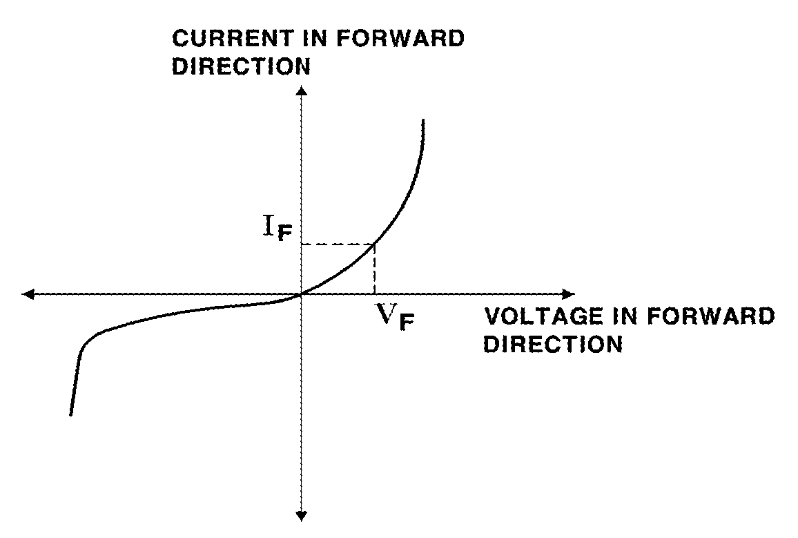
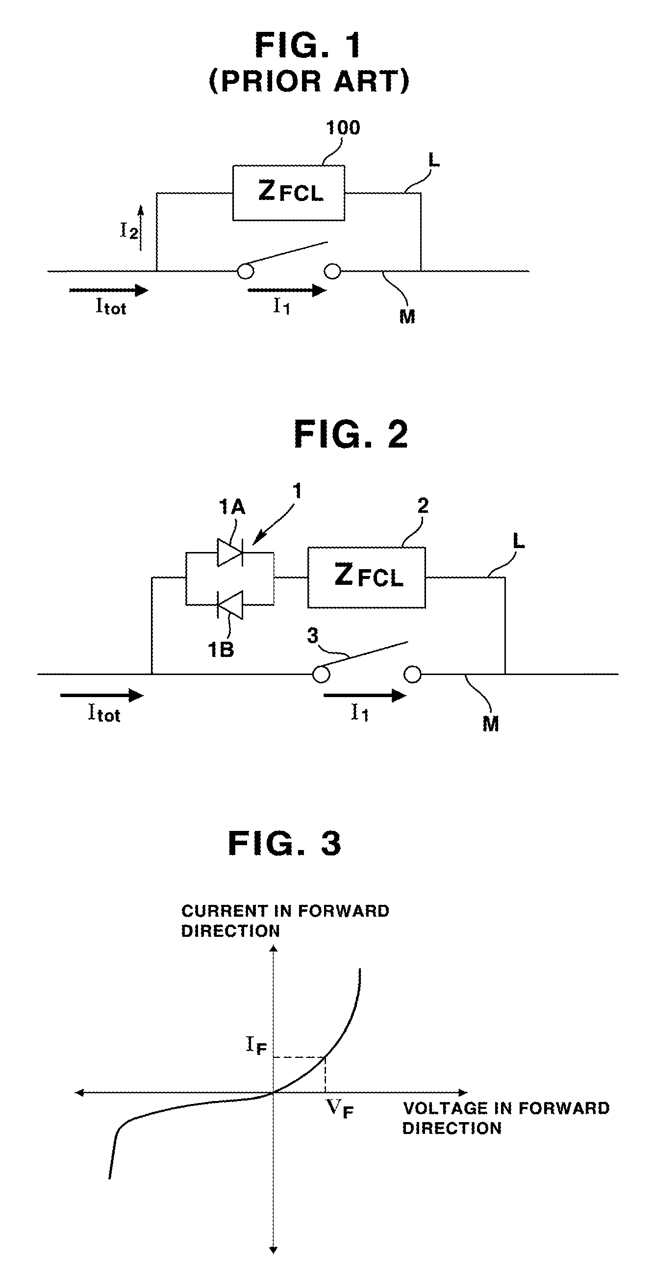
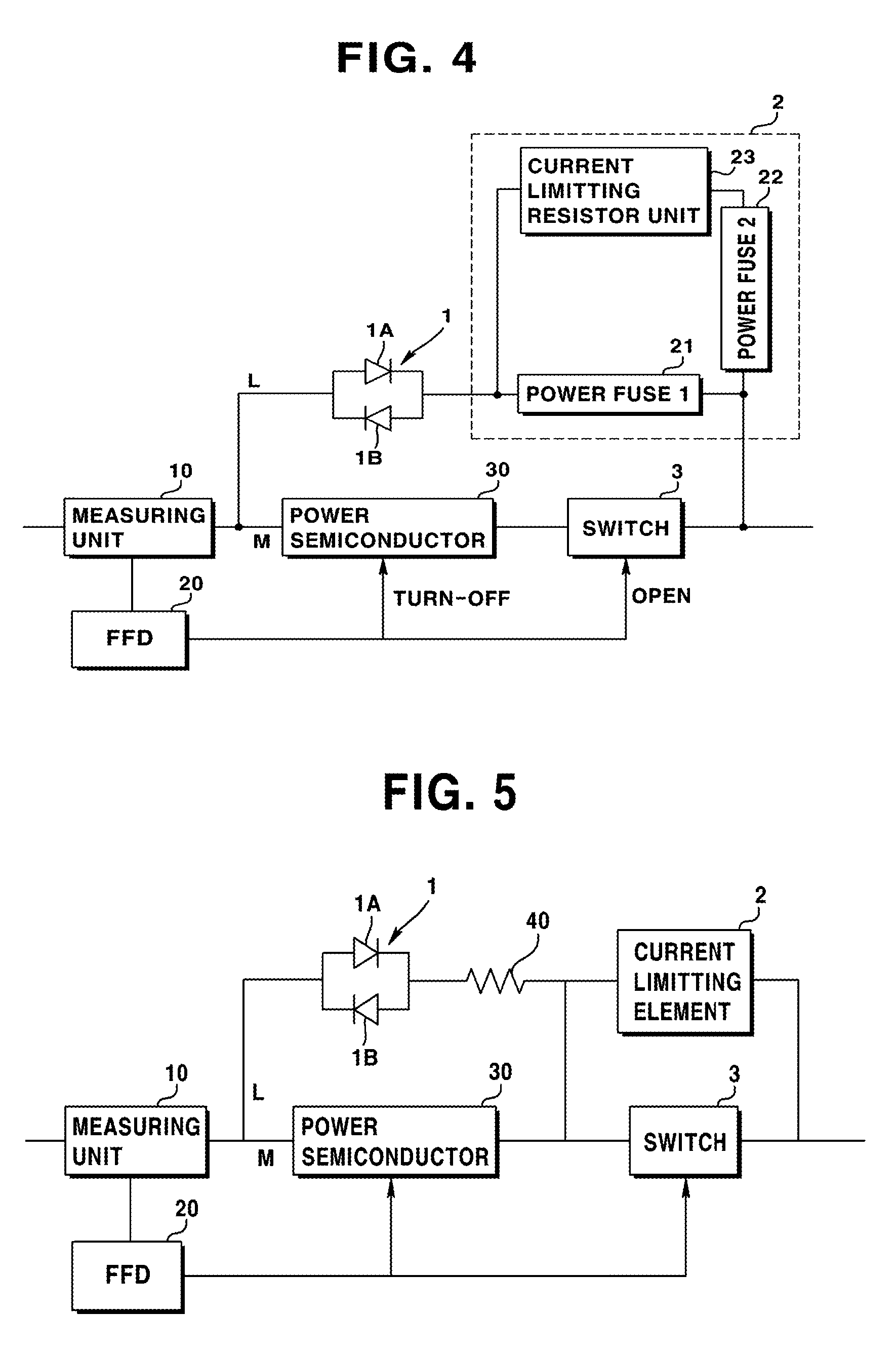
[0033]The fault current limiter according to an embodiment of the present disclosure designs breakdown voltage of the diode on the limiting path to be higher than voltage drop of the main path, by using a power diode. That is, by designing the breakdown voltage of the diode on the limiting path to be higher than voltage drop of the main path, while no current flows to the limiting path the in a normal state, a fault current may be switched to detour from the main path to the...


PUM


Abstract

A fault current limiter is provided. According to an embodiment of the present disclosure, the fault current limiter includes a switch whose contact point is opened when a fault current occurs; a current limiting element configured to limit the fault current when the fault current occurs; and a diode being serial-connected to the current limiting element, wherein a breakdown voltage of the diode is higher than a voltage drop by an impedance of the switch when a normal current flows.

Description

CROSS-REFERENCE TO RELATED APPLICATION[0001]Pursuant to 35 U.S.C. §119(a), this application claims the benefit of earlier filing date and right of priority to Korean Application No. 10-2013-0138990, filed on Nov. 15, 2013, the contents of which is incorporated by reference herein in its entirety.BACKGROUND[0002]1. Field of the Disclosure[0003]The present disclosure relates to a fault current limiter. More specifically, the present disclosure relates to a fault current limiter used in a system such as electric power equipment.[0004]2. Description of Related Art[0005]Generally, a fault current limiter is a device protecting equipment in an electric power system by converting fault current (which occurs in accidents such as thunderstroke, grounding, and short-circuit) into normal current. Recently, various types of fault current limiters are used in related fields. The types of fault current limiter may be categorized by elements used therein, for a non-limiting example, superconductor...

Claims


Application Information

Patent Timeline
Patent Type & Authority Patents(United States)
IPC IPC(8): H02H9/02H01H9/54H01H33/02H02H3/08H02H3/02
CPCH02H9/02H01H9/54H01H33/02H02H3/08H02H9/026H02H3/025H01H9/56H01H33/59H02H9/00H02H9/08H03K17/725H03K17/78
Inventor SIM, JUNG WOOKLEE, GYEONG HOPARK, HAE YONG
Owner LSIS CO LTD
Why Eureka
Try Eureka