Adaptive Adjustable Inrush Current Limiter

A technology of self-adaptive regulation and inrush current, applied in relays, circuits, emergency protection circuit devices for limiting overcurrent/overvoltage, etc. higher question

Active Publication Date: 2022-07-19
MEANWELL GUANGZHOU ELECTRONICS +1
View PDF0 Cites 0 Cited by
  • Summary
  • Abstract
  • Description
  • Claims
  • Application Information

AI Technical Summary

Problems solved by technology

[0004] In more detail, when having figure 1 When a power supply unit (PSU) of the inrush current limiter 1' is in operation, if the startup time (Setup time) of the power supply unit is less than the pull-in time of the relay 12', the power supply unit will The relay 12' is activated many times before the pull-in action is performed, causing a large current to continuously flow through the current-limiting resistor, thereby causing the temperature of the current-limiting resistor to be too high, and finally causing the fuse of the power supply unit to be blown
[0005] As can be seen from the above description, the existing inrush current limiter 1' comprising the control unit 13' still has room for further improvement

Method used


Image

  • Adaptive Adjustable Inrush Current Limiter
  • Adaptive Adjustable Inrush Current Limiter
  • Adaptive Adjustable Inrush Current Limiter

Examples


Embodiment Construction

[0097] In order to be able to describe the self-adaptive inrush current limiter proposed by the present invention more clearly, the preferred embodiments of the present invention will be described in detail below with reference to the drawings.

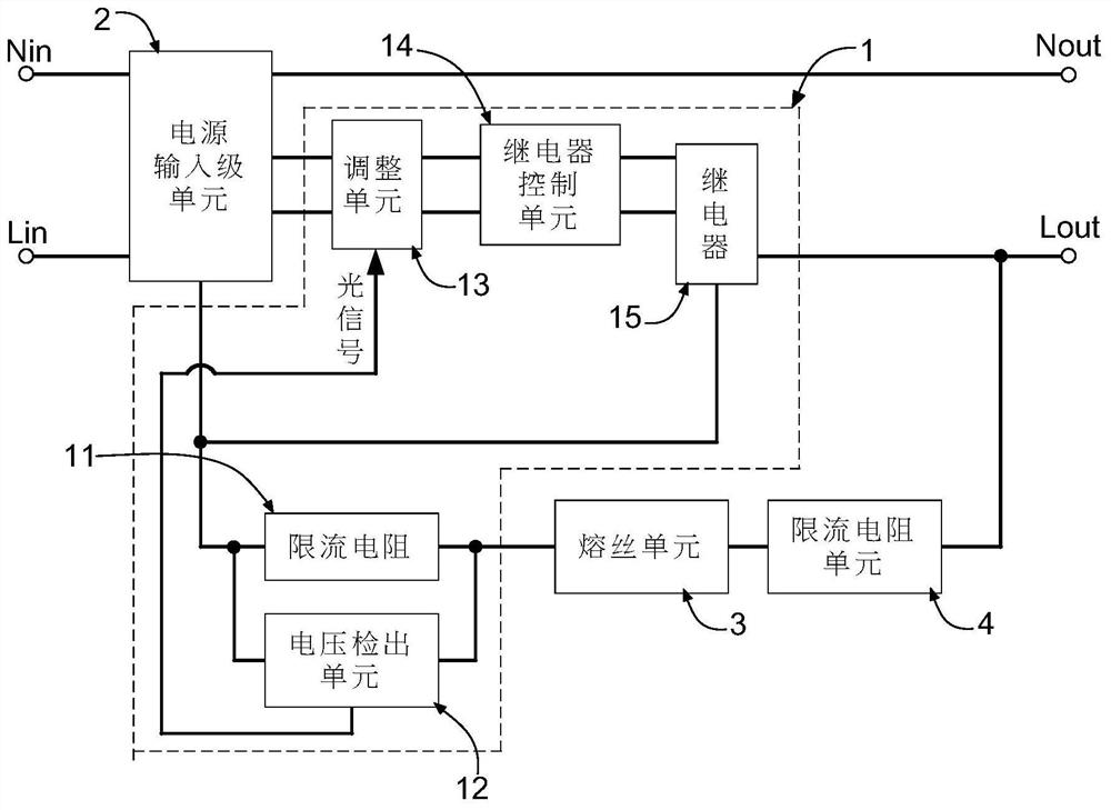
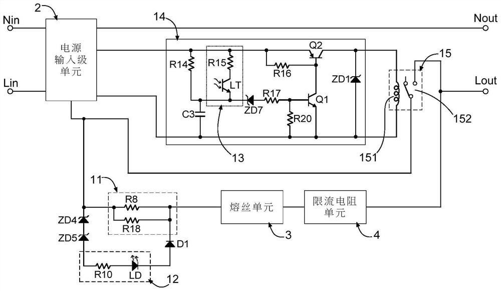
[0098] figure 2 showing a circuit block diagram of an adaptively adjusted inrush current limiter of the present invention, and image 3 A first circuit topology diagram of the self-adapting inrush current limiter of the present invention is shown. like figure 2 and image 3 As shown, the adaptively adjusted inrush current limiter 1 of the present invention is applied in a power conversion circuit, wherein the power conversion circuit is included in a power supply, a power converter, or an LED driving power device , and has a power input stage unit 2 . In more detail, the power input stage unit 2 is coupled to a live wire input terminal Lin, a live wire output terminal Lout, a neutral wire input terminal Nin, and a neutral wire o...


PUM


Abstract

The present invention comprises at least a current limiting resistor, a voltage detection unit, an adjustment unit, a relay control unit, and a relay to form an adaptively adjusted surge current limiter. In particular, when the start-up time of a power supply unit including the inrush current limiter is less than the pull-in time of the relay, the adjustment unit will depend on whether a resistance voltage detected by the voltage detection unit exceeds a threshold value And output an adjustment signal to the relay control unit, so that the relay control unit controls the relay to perform a pull-in switching operation in advance. On the contrary, when the start-up time of the power supply device is greater than the pull-in time of the relay, the relay control unit will control the relay to perform the pull-in switching operation after a delay time has elapsed. In short, the inrush current limiter of the present invention can adaptively adjust the pull-in time of the relay according to the different start-up times of different power supply devices.

Description

technical field [0001] The present invention relates to the related technical field of power supply devices, in particular, to a surge current limiter coupled between an AC power supply and a main power supply unit (PSU). In particular, the inrush current limiter can adaptively adjust the pull-in time of its internal relay according to the specific start-up time of the matched PSU. Background technique [0002] The input end of the Switch Mode Power Supply (SMPS) is usually equipped with a bulk capacitor, which is used for filtering and rectifying the input AC power together with the bridge rectifier. However, this large capacitor will be equivalent to a short circuit when the switching power supply is turned on, thus generating a large inrush current. Therefore, the traditional approach is to use a negative temperature coefficient (NTC) resistor to suppress this inrush current, however this simple method has many disadvantages including: (1) the current limiting effect is ...

Claims


Application Information

Patent Timeline
Patent Type & Authority Patents(China)
IPC IPC(8): H02H9/02H01H47/02H01H47/18H02M1/32
CPCH02H9/02H01H47/02H01H47/18H02M1/32
Inventor 陈鹤鸣
Owner MEANWELL GUANGZHOU ELECTRONICS
Why Eureka
Try Eureka