Inrush current limiter

An inrush current and limiter technology, applied in electrical components, circuit devices, emergency protection circuit devices for limiting overcurrent/overvoltage, etc., can solve the problem that the thermistor cannot simultaneously reduce the inrush current, increase, cannot Satisfaction etc.

Inactive Publication Date: 2011-08-10
GLACIALTECH +1
View PDF0 Cites 0 Cited by
  • Summary
  • Abstract
  • Description
  • Claims
  • Application Information

AI Technical Summary

Problems solved by technology

However, practical thermistors cannot satisfy both requirements of an ideal thermistor
That is, practical thermistors cannot simultaneously reduce inrush current and power dissipation
To make matters worse, R initial Decrease with increasing temperature will result in increases with increasing temperature
In other words, if the power supply is turned on at high temperature, the thermistor cannot fully perform the function of the inrush current limiter

Method used


Image

  • Inrush current limiter
  • Inrush current limiter
  • Inrush current limiter

Examples


Embodiment Construction

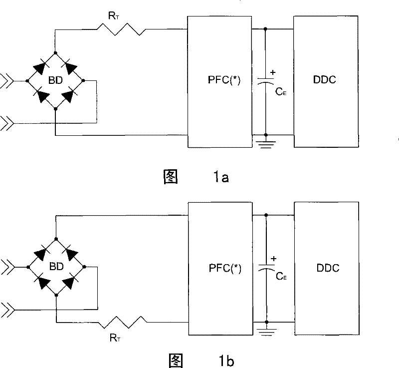
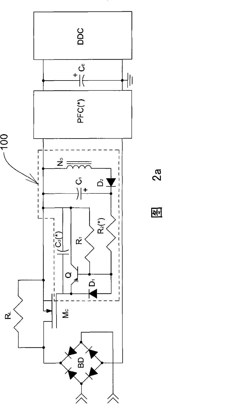
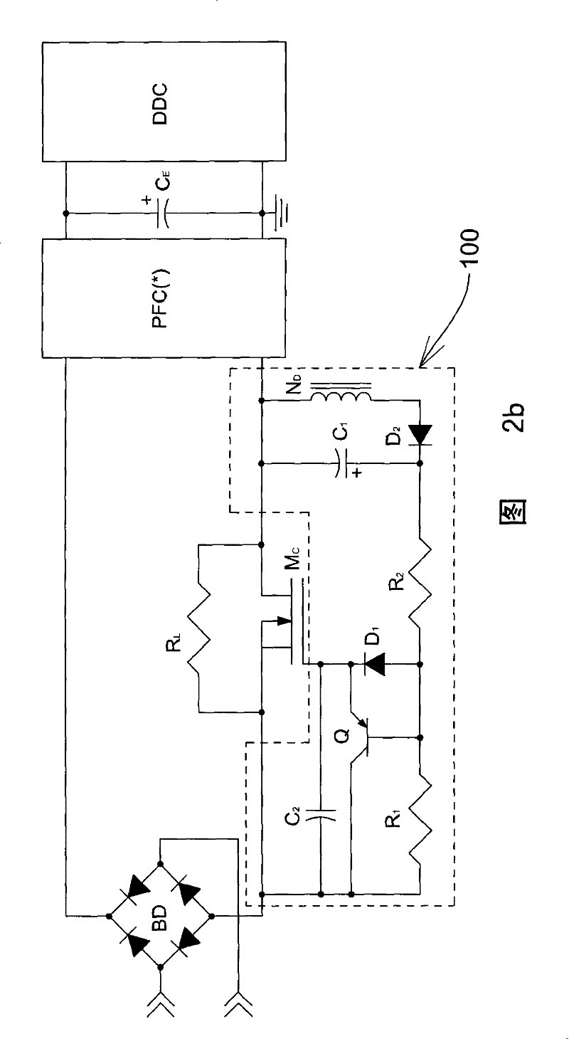
[0021] The basic circuit diagrams of the high-voltage side inrush current limiter and the low-voltage side inrush current limiter disclosed in the present invention are shown in Figure 2a and Figure 2b , the current limiting resistor R L Connected to an N-channel metal-oxide-semiconductor field-effect transistor (NMOSFET) M C Between the receiving end (drain) and the discharging end (source), the gate driver 100 is connected to M C between the gate and source. The gate driver consists of a transistor Q connected to the M C The gate and source of Q are realized by PNP bipolar transistors in the embodiment. The second capacitance C 2 The positive and negative poles of Q are connected to the emitter and collector of Q respectively. first diode D 1 The anode and cathode of the resistor are respectively connected to the base and emitter of Q, and the first resistor R 1 Connect the collector and base of Q. The first capacitance C 1 The negative pole and positive pole of ...


PUM


Abstract

The invention discloses an inrush current limiter in a power supply, comprising a resistor, a field effect transistor and a gate driver. In a startup moment of the power supply, the gate driver does not start the field effect transistor so that an inrush current passes by the resistor and the resistance is limited to a safety value; and in a steady state of the power supply, the field effect transistor is already started by the gate driver so that a steady state current passes by the field effect transistor and the power dissipation is reduced by the field effect transistor to a minimum.

Description

technical field [0001] The present invention discloses an inrush current limiter in a power supply, which utilizes a resistor to limit the inrush current and a field effect transistor to conduct the steady state current. Background technique [0002] When the power supply is turned on, the current flowing into the power supply is called inrush current. In order to protect the power supply from being damaged by the inrush current, an inrush current limiter is usually used to limit the inrush current to a safe value. [0003] The circuit diagrams of the existing high-side inrush current limiter (high-side inrush current limiter) and low-voltage side inrush current limiter (low-side inrush current limiter) implemented by thermistor are shown in Figure 1a and Figure 1b , where the bridge rectifier BD is used to rectify the AC sine wave input voltage into a DC sine wave input voltage; the thermistor R with a negative temperature coefficient (negative temperaturecoefficient) T...

Claims


Application Information

Patent Timeline
Patent Type & Authority Patents(China)
IPC IPC(8): H02M1/32H02H9/02
Inventor 王志良余金生翁博泰
Owner GLACIALTECH
Why Eureka
Try Eureka