Control method and device for narrow pulse filter, storage device and narrow pulse filtering equipment

A control method and narrow pulse technology, applied in the computer field, can solve the problems of high power dissipation, damage to the switch tube, and reduce the overall circuit work efficiency, and achieve the effect of improving work efficiency and reducing power dissipation.

Active Publication Date: 2018-03-06
GUANGZHOU SHIYUAN ELECTRONICS CO LTD +1
View PDF9 Cites 3 Cited by
  • Summary
  • Abstract
  • Description
  • Claims
  • Application Information

AI Technical Summary

Problems solved by technology

Since the PWM signal controlling the switching tube has a narrow pulse, the duty ratio of the narrow pulse is relatively small, and since the switching tube is in a linear state when the PWM signal is on the rising edge and falling edge, the time for the switching tube to be in the linear region at this time takes up The proportion of the total on-time of the switch tube is relatively high, and beca...

Method used


Image

  • Control method and device for narrow pulse filter, storage device and narrow pulse filtering equipment
  • Control method and device for narrow pulse filter, storage device and narrow pulse filtering equipment
  • Control method and device for narrow pulse filter, storage device and narrow pulse filtering equipment

Examples


Embodiment 1

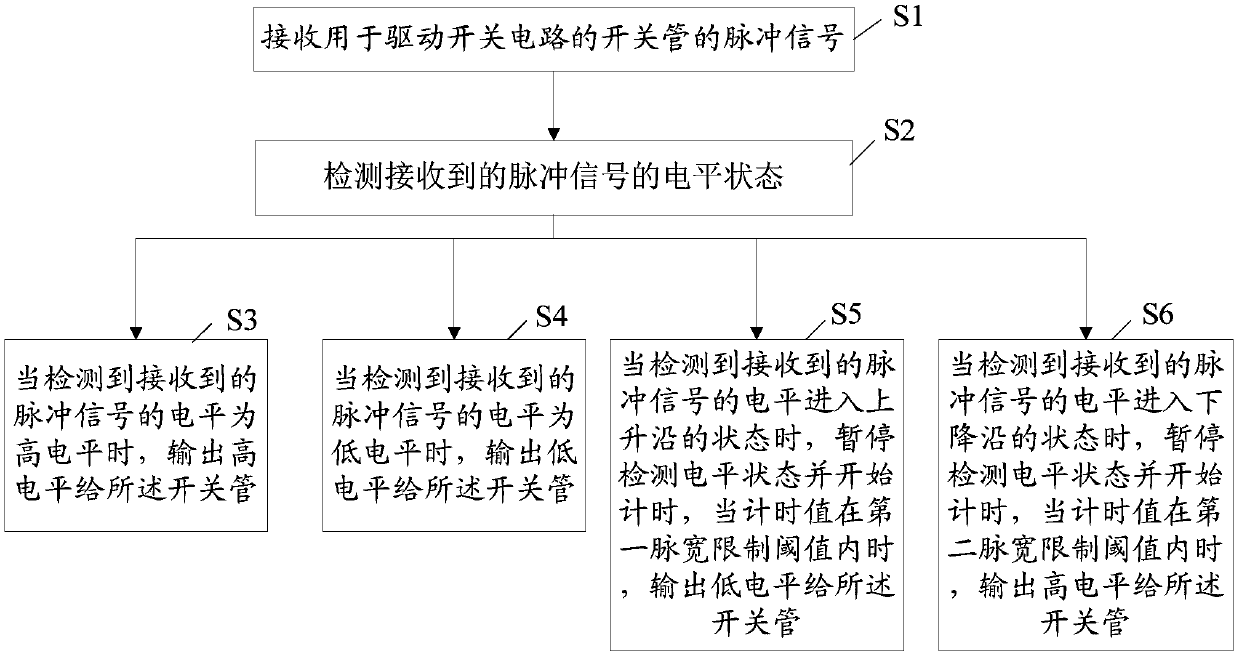
[0061] see image 3 , is a schematic flow chart of an embodiment of the narrow pulse filtering control method provided by the present invention; the narrow pulse filtering control method is executed by the control processor, including steps S1 to S6, specifically as follows:

[0062] S1, receiving the pulse signal used to drive the switch tube of the switch circuit. This pulse signal is a pulse signal generated by a signal generator, and the pulse signal received in step S1 is a momentary signal received at the current moment, and the control processor continues to receive the pulse signal at each moment, then the received Changing pulse signals such as figure 1 and figure 2 As shown, the input pulse timing signal may include a narrow pulse at a high level and a narrow pulse at a low level. The pulse timing signal is used to drive the switching tube. When the pulse signal is in the state of rising edge and falling edge, the switching tube is in the linear region, and when ...

Embodiment 2

[0084] see Figure 4 , is a schematic structural diagram of an embodiment of the control device for narrow pulse filtering provided by the present invention; the embodiment of the present invention provides a control device for narrow pulse filtering, which can realize the entire flow of the control method for narrow pulse filtering provided in the above embodiments , including:

[0085]A signal receiving module 10, configured to receive a pulse signal for driving a switching tube of a switching circuit;

[0086] Level detection module 20, for detecting the level state of the received pulse signal;

[0087] The first level output module 30 is configured to output a high level to the switch tube when it is detected that the level of the received pulse signal is a high level;

[0088] The second level output module 40 is configured to output a low level to the switch tube when it is detected that the level of the received pulse signal is low level;

[0089] The third level ou...

Embodiment 3

[0105] see Figure 7 , is a schematic flow chart of another embodiment of the narrow pulse filtering control method provided by the present invention; the narrow pulse filtering control method is executed by the control processor, including steps S11 to S17, specifically as follows:

[0106] S11, receiving a pulse signal for driving a switching tube of a switching circuit;

[0107] S12, detecting the level state of the received pulse signal;

[0108] S13, outputting a high level to the switch tube when it is detected that the level of the received pulse signal is a high level;

[0109] S14, when it is detected that the level of the received pulse signal is a low level, outputting a low level to the switch tube;

[0110] S15, when it is detected that the level of the received pulse signal enters the rising edge state, start the first timer to start counting, when the timing value of the first timer is within the first pulse width limit threshold, and no pulse width is detecte...


PUM


Abstract

The invention discloses a control method and device for narrow pulse filter, a storage device and narrow pulse filtering equipment. The method comprises the following steps: receiving a pulse signal used for driving a switching tube of a switching circuit; detecting the level state of the received pulse signal; when detecting that the level of the received pulse signal is a high level or a low level, outputting the corresponding high level or low level to the switching tube; when detecting that the level of the received pulse signal goes into the state of a rising edge, pausing to detect the level state and starting to time, and when a timing value is within a first pulse width limit threshold, outputting the low level to the switching tube; and when detecting that the level of the received pulse signal goes into the state of a falling edge, pausing to detect the level state and starting to time, and when the timing value is within a second pulse width limit threshold, outputting the high level to the switching tube. The control method for the narrow pulse filter provided by the embodiment of the invention reduces the dissipation power of the switching tube, improves the overall working efficiency of a circuit, and adjusts the output pulse width.

Description

technical field [0001] The invention relates to the field of computer technology, in particular to a control method and device for narrow pulse filtering, storage equipment and narrow pulse filtering equipment. Background technique [0002] For an ideal PWM (Pulse Width Modulation, pulse width modulation) signal, such as figure 1 The duty cycle D shown is Ton / T, that is, the ratio of the conduction time to the entire PWM waveform period. And the actual PWM signal waveform is as figure 1 As shown, there are rising and falling edges during the turn-on period. [0003] For the switching tube of the switching tube driving circuit, the switching tube is a semiconductor device, usually including a triode, a field effect tube, an IGBT tube, a GTO, a GTR, etc., and the dissipation power of the switching tube is P=U*I, and U is the power at both ends of the switching tube. Voltage, I is the current flowing through the switch tube. When the switch tube is cut off, I is about zero,...

Claims


Application Information

Patent Timeline
IPC IPC(8): H03K5/04H03K7/08
CPCH03K5/04H03K7/08
Inventor 梁军蒲周平杨莲科
Owner GUANGZHOU SHIYUAN ELECTRONICS CO LTD
Why Eureka
Try Eureka