
Opto-Isolator Multi-Voltage Detection Circuit

Active Publication Date: 2009-11-26
FISHER CONTROLS INT LLC
View PDF18 Cites 3 Cited by
  • Summary
  • Abstract
  • Description
  • Claims
  • Application Information

AI Technical Summary

Benefits of technology

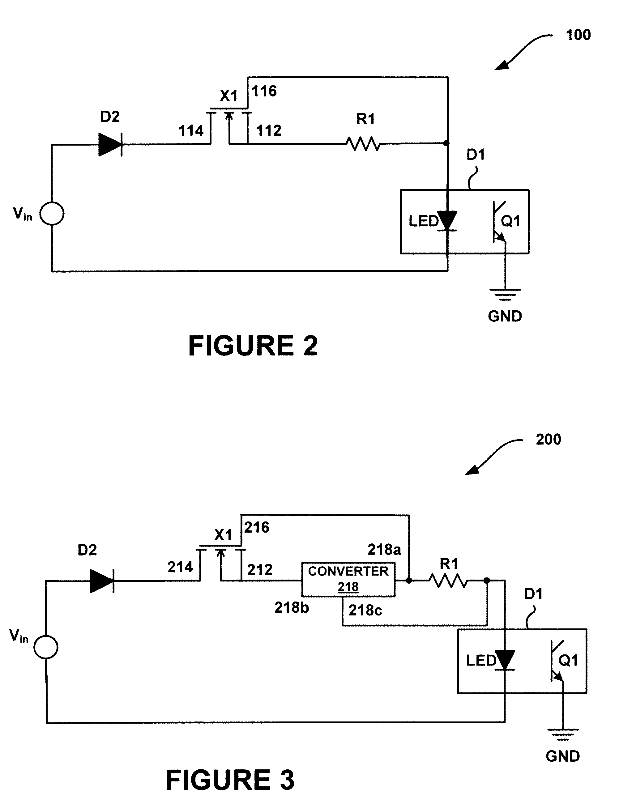
[0005]The opto-isolator multi-voltage detection circuit may further incorporate a converter such as a DC to DC converter. The DC to DC converter may provide the further benefit of reducing system crosstalk and power dissipation.
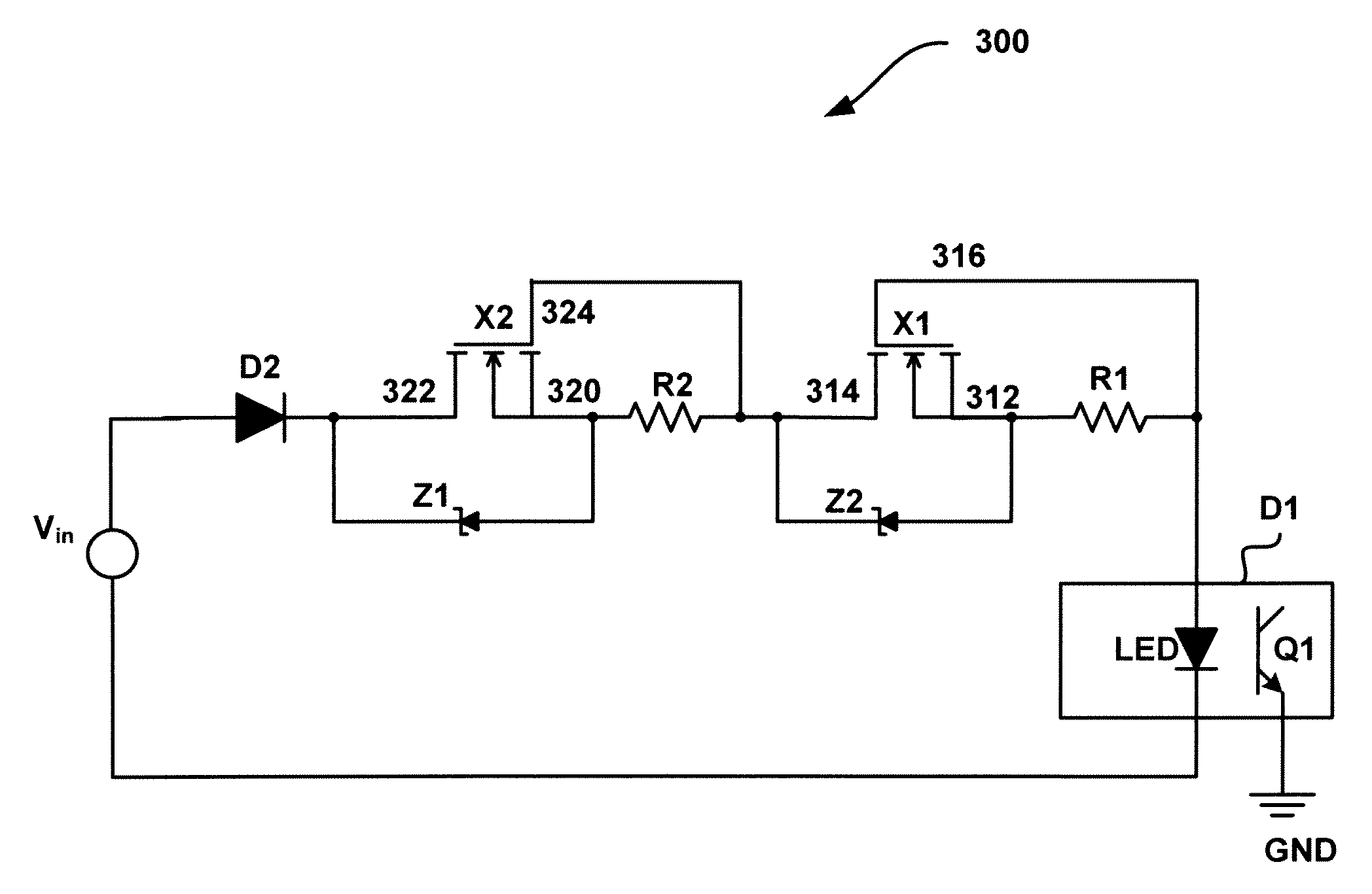
[0006]The opto-isolator multi-voltage detection circuit may further incorporate a second transistor and a voltage divider. The voltage divider may be operatively coupled to the first and second transistors and is configured to divide the input voltage across the first and second transistors. The voltage divider may provide the further benefit of reducing the power dissipated through the first and second transistors.
[0007]According to another aspect of the invention, an opto-isolator multi-voltage detection circuit for use with 9 volt DC through 240 volt AC input voltages from a voltage source includes a diode, first and second transistors, two zener diodes, and an opto-isolator coupled to the first and second transistors. The zener diodes may limit the input voltage to the first and second transistors providing an overall reduction in power dissipation and system crosstalk.

Problems solved by technology

The use of the sensing resistor may be undesirable in some applications because the resistor must handle an excessive power dissipation which leads to high impedance noise pulses.
Unfortunately, a sensing resistor is expensive, and typically dissipates a substantial amount of heat.

Method used


Image

  • Opto-Isolator Multi-Voltage Detection Circuit
  • Opto-Isolator Multi-Voltage Detection Circuit
  • Opto-Isolator Multi-Voltage Detection Circuit

Examples


Embodiment Construction

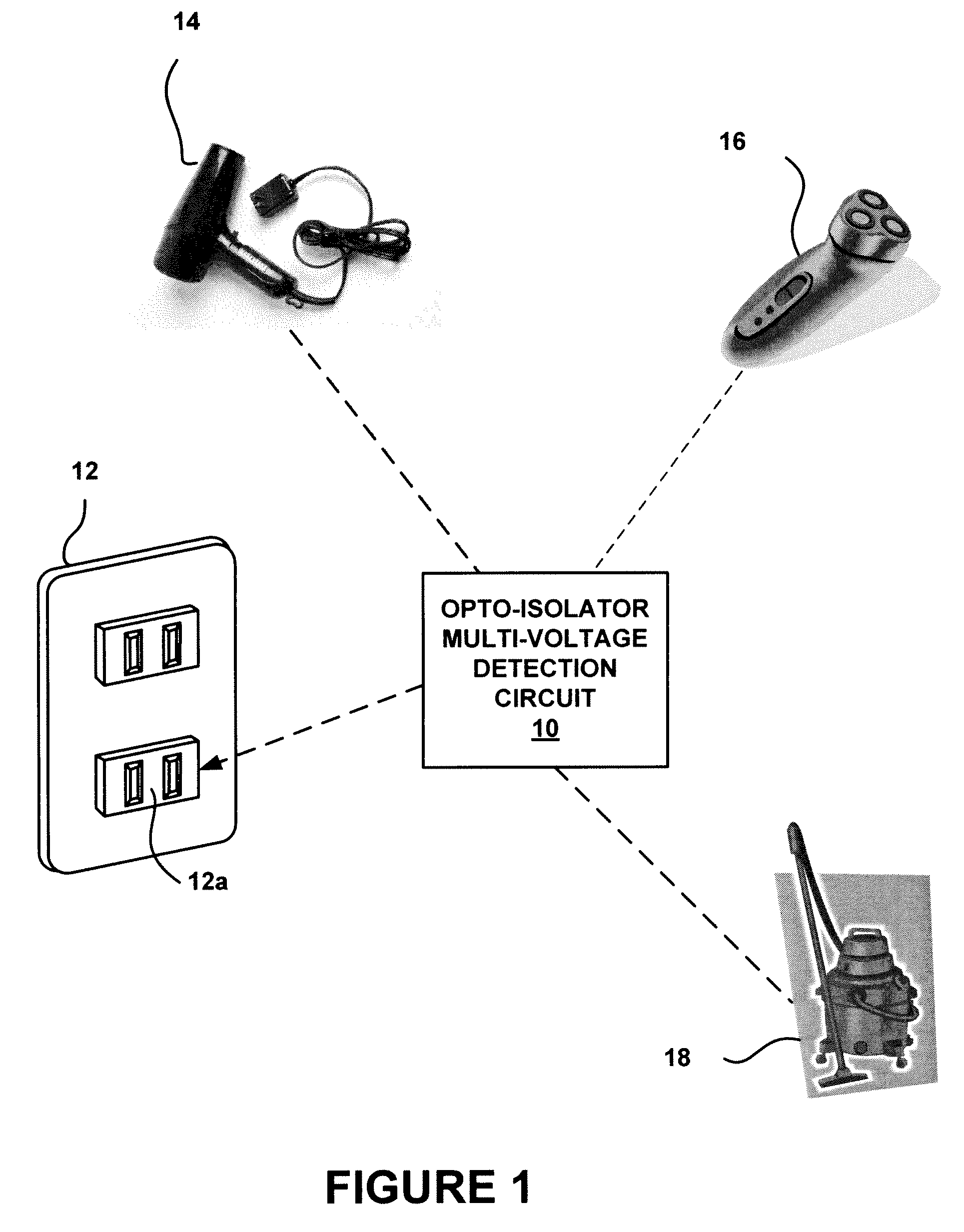
[0016]FIG. 1 schematically depicts an exemplary opto-isolator multi-voltage detection circuit 10 assembled in accordance with the teachings of the invention. The circuit 10 may be used to connect any one of a variety of electronic devices to a voltage source 12. The circuit 10 may be a stand-alone circuit that connects virtually any type of electronic device to a socket 12a of the voltage source 12. Alternatively, the circuit 10 may be a built-in circuit disposed inside the electronic device, with the electronic device directly connectable to the socket 12a. Exemplary electronic devices include a hair dryer 14, a shaver 16, a vacuum cleaner 18 or other consumer electronic devices.

[0017]FIG. 2 depicts an exemplary opto-isolator multi-voltage detection circuit 100 assembled in accordance with the teachings of the invention. The circuit 100 includes an opto-isolator D1, which is preferably part number HCPL-2360, as sold by Avago Technologies Limited. Typically, the opto-isolator D1 inc...


PUM


Abstract

An opto-isolator multi-voltage detection circuit is capable to handle a wide range of input voltages ranging from about 9 volts DC to about 240 volts AC includes an input voltage, an opto-isolator, a rectifier, a voltage divider, first and second transistors, and a DC to DC converter. The voltage divider operatively coupled to the first and second transistors is capable of evenly dividing the input voltage across the first and second transistors. The DC to DC converter operatively coupled to the transistors, the voltage divider, and the opto-isolator is capable of maintaining an output current from the rectifier. The use of the DC to DC converter, the voltage divider, and the transistors provide benefit of reducing a power dissipated throughout the entire circuit.

Description

FIELD OF THE INVENTION[0001]The present invention relates to voltage detection devices and, more particularly, to an opto-isolator multi-voltage detection circuit that provides voltage detection.BACKGROUND[0002]There exists a wide variety of power sources for powering electronic devices. For example, in the United States and Japan the standard AC voltage is 10V, while the AC standard voltage in Europe, Australia and other countries is 240V. When connecting an electronic device to a power source or any electric circuit, it may be beneficial to confirm the presence of the required voltage to the electronic device.[0003]Presently, available low voltage detector circuits are used to detect the presence of a voltage from a power source. An opto-isolator is an electrical component typically used in a low voltage detector circuit to optically transfer a signal between an input and an output circuit, such as between a low voltage and a high voltage circuit. The opto-isolator helps to electr...

Claims


Application Information

Patent Timeline
IPC IPC(8): H05B37/00
CPCG01R15/22G01R19/16519G01R19/155
Inventor EISENBEIS, CLYDE T.SEBERGER, STEPHEN G.
Owner FISHER CONTROLS INT LLC
Learn More