LED drive circuit

A technology of LED drive and circuit, applied in the direction of lamp circuit layout, electric light source, lighting device, etc., can solve the problems of high working voltage, affecting the stability of driving circuit, high power consumption, etc.

Pending Publication Date: 2016-08-03
汤崟
View PDF0 Cites 3 Cited by
  • Summary
  • Abstract
  • Description
  • Claims
  • Application Information

AI Technical Summary

Problems solved by technology

However, the main disadvantage of the linear constant current drive circuit is that when the input voltage rises, the constant current drive control device will bear higher operating voltage and greater power consumption, which will increase the temperature rise of the

Method used


Image

  • LED drive circuit
  • LED drive circuit
  • LED drive circuit

Examples


Embodiment Construction

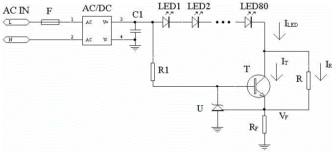
[0015] figure 2 It is an embodiment of the LED driving circuit according to the present invention. The reference reference voltage and the operational amplifier are replaced by a parallel three-terminal voltage regulator TL431. The characteristic of this circuit is that the output current stability accuracy is relatively high.

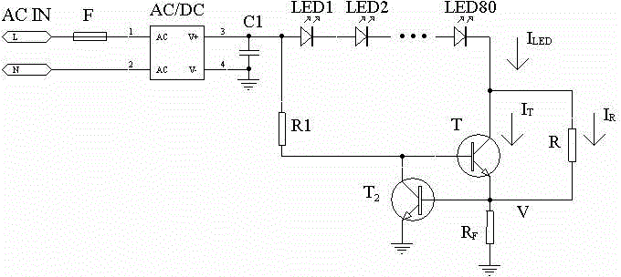
[0016] image 3 It is another embodiment of the LED driving circuit according to the present invention. This is a low cost circuit that uses all bipolar transistors. The characteristic of this circuit is that the output current has a negative temperature coefficient. This is very beneficial to reduce the light attenuation of the LED of the light source module.

[0017] Figure 4 It is another embodiment of the LED driving circuit according to the present invention. Among them, IC is a high-voltage linear constant current integrated circuit. In this circuit, since the constant current output adjustment tube, current detection and operational amp...


PUM


Abstract

The LED drive circuit of the present invention is a high-voltage LED linear constant current drive circuit, which is composed of two parts, an AC/DC conversion circuit AC/DC and a linear constant current source circuit, in addition to the LED light source module. The linear constant current source circuit part mainly includes amplifier A, constant current output adjustment tube T, reference reference power supply Vfer, working power supply VDD, output current sampling resistor R F and output current shunt resistor R. The LED drive circuit of the present invention, when the constant current output adjustment tube T is subjected to voltage rise, bypasses a part of the output current through the shunt resistor R connected in parallel with the output terminal of the constant current adjustment tube T, so as to reduce the power dissipation of the constant current adjustment tube T , reduce temperature rise and improve stability. The higher the voltage withstood by the output end of the constant current adjusting tube T, the greater the bypass current of the shunt resistor R. As long as you choose the appropriate shunt resistor resistance, and arrange the shunt resistor reasonably to keep it away from thermally sensitive devices, and control the temperature rise of the constant current regulator tube within a safe range, the stability of the constant current drive circuit can be improved and the expansion can be extended. scope of application.

Description

technical field [0001] The invention relates to the field of electronic circuits, in particular to a high-voltage linear constant-current LED lighting drive circuit. Background technique [0002] The existing high-voltage LED lighting drive circuit has three basic forms: capacitor step-down circuit, switch constant current drive circuit and linear constant current drive circuit. The three driving circuits each have their own advantages and disadvantages. Among them, the linear constant current driving circuit is widely used because of its low cost, small size, easy assembly, and the ability to be installed on the same circuit board as the LED. However, the main disadvantage of the linear constant current drive circuit is that when the input voltage rises, the constant current drive control device will bear higher operating voltage and greater power consumption, which will increase the temperature rise of the control device and affect the The stability of the entire drive ci...

Claims


Application Information

Patent Timeline
IPC IPC(8): H05B37/02
Inventor 汤亦蕾
Owner 汤崟
Why Eureka
Try Eureka