Wireless packet communication method and wireless packet communication apparatus

a wireless packet and communication method technology, applied in the field of wireless packets, can solve the problems of preventing the reception of ack packets, affecting the influence of the leakage power of the other wireless channel being used for simultaneous transmission, and no improvement in throughput can be expected

Active Publication Date: 2011-07-05
NIPPON TELEGRAPH & TELEPHONE CORP
View PDF32 Cites 35 Cited by
  • Summary
  • Abstract
  • Description
  • Claims
  • Application Information

AI Technical Summary

Problems solved by technology

When the transmit-side STA attempts to receive this acknowledgement packet (hereinafter, ACK packet), the influence of the leakage power from the other wireless channel being used for the simultaneous transmission poses a problem.
Therefore, there is a possibility that leakage power from the wireless channel #2 may prevent the reception of the ACK packet via the wireless channel #1.
Under such circumstances, no improvement in throughput can be expected even in the simultaneous transmission using the multiple wireless channels.
Meanwhile, in a wireless LAN system and the like, data size of data frames inputted from a network is not constant.
Consequently, as shown in FIG. 48, even if the plural data packets are simultaneously transmitted, there is a higher possibility of a failure in receiving the ACK packet, due to the difference in the packet time length between the data packets.
Two idle wireless channels are not always available when retransmission processing is thereafter executed due to a failure of transmission of at least one of the data packets.
At this time, carrier sense is necessary before each of the retransmission packets is transmitted, and thus it is not always possible to transmit them continuously, which may possibly cause reduced throughput, increased average delay time, and increased jitter.
Next, problems when conventional retransmission methods are applied to simultaneous transmission will be described, though a retransmission method in the simultaneous transmission will not be particularly specified.
This means that the data packet successfully transmitted is also retransmitted, so that channel utilization is lowered and throughput is unavoidably lowered.
In a MIMO system in particular, if the number of multiplexing is increased, the influence that a fluctuation in wireless channels gives to transmission quality becomes more significant, resulting in a higher packet error rate and a higher bit error rate.
Therefore, if all data packets including data packets which have been successfully transmitted are simultaneously retransmitted due to the failure of part of the data packets that have been simultaneously transmitted, a probability of another transmission failure becomes high, so that channel utilization and throughput have been unavoidably lowered.
Then, at the next transmission timing t2, it simultaneously transmits data packets P4, P5 that have been simultaneously generated since the retransmission of only the not-successfully-transmitted data packet P2 leads to poor efficiency.

Method used


Image

  • Wireless packet communication method and wireless packet communication apparatus
  • Wireless packet communication method and wireless packet communication apparatus
  • Wireless packet communication method and wireless packet communication apparatus

Examples


tenth embodiment

[0158]FIG. 13 shows a flowchart of a tenth embodiment of the present invention. This embodiment is characterized in that simultaneous transmission using multiple wireless channels or simultaneous transmission using a MIMO system is selected according to the number of data arriving in a transmission buffer or the number of MIMOs that depends on a channel condition (S231). In response to this selection, the data is reconstructed to packets with the same length according to the number of the idle channels (or the number of MIMOs), and the reconstructed packets are assigned to the respective wireless channels (or respective antennas of the MIMO) to be (simultaneously) transmitted (S232).

[0159]Next, it is confirmed for all the simultaneously transmitted packets whether or not ACK packets are received within a predetermined time after the transmission (S204), and a packet for which the ACK packet is not received within the predetermined time is subjected to retransmission processing (S205...

eleventh embodiment

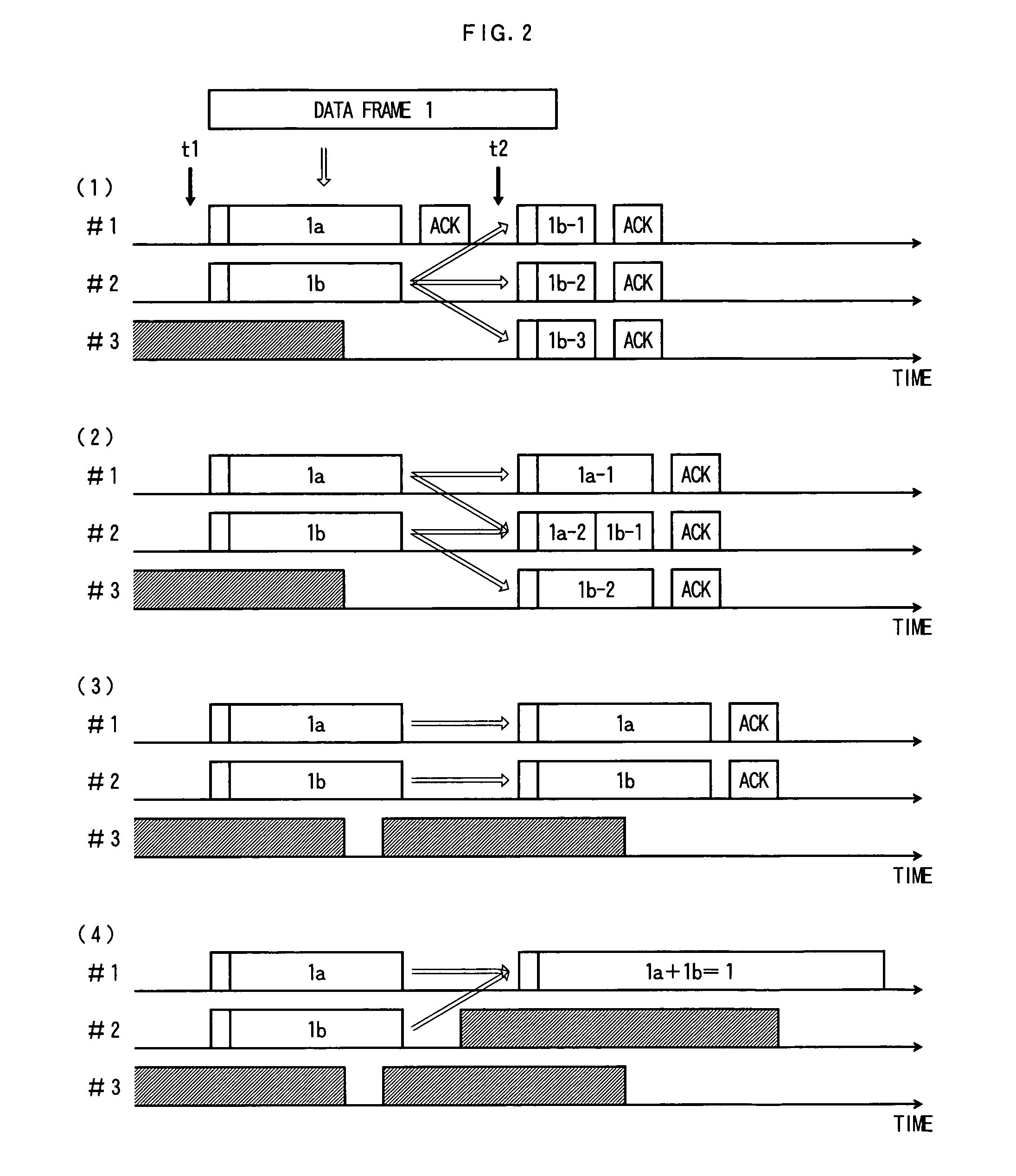
[0165]FIG. 15 shows a flowchart of an eleventh embodiment of the present invention. FIG. 16 shows an operation example of the eleventh embodiment of the present invention. It is assumed here that wireless channels #1, #2, #3 are prepared.

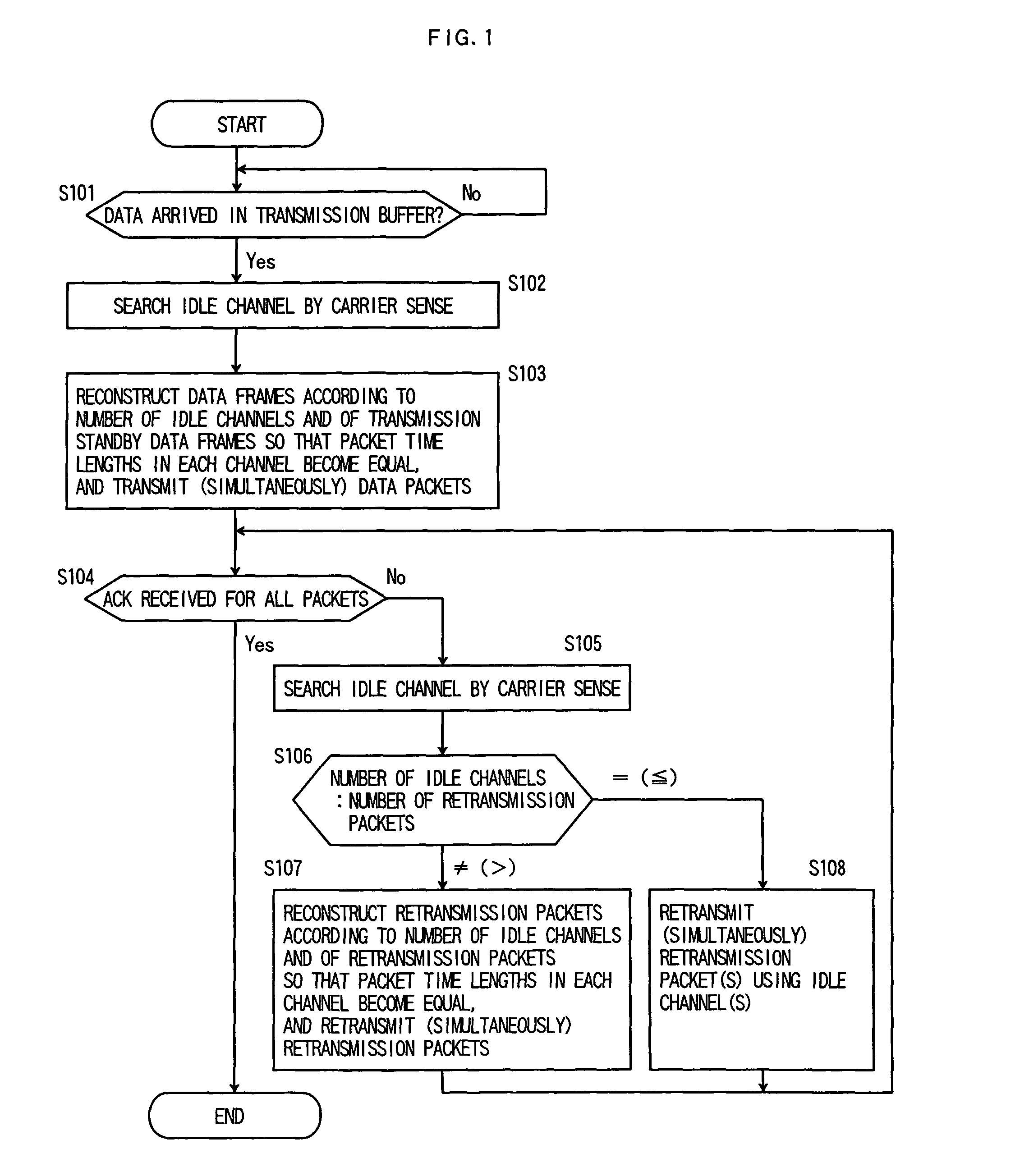
[0166]When data arrives in a transmission buffer, it is first searched by carrier sense if there is any idle wireless channel (S301, S302). In FIG. 16, at a timing the data is generated t1, the wireless channel #3 is busy, and the wireless channel #1 and the wireless channel #2 are retrieved as idle. Next, according to the number of the idle channels and the number of transmission-standby data packets, packets are generated by, for example, any one of the methods shown in FIG. 49, so that the packet time lengths in the respective wireless channels become equal, and the data packets are assigned to the respective wireless channels to be (simultaneously) transmitted (S303).

[0167]In the example shown in FIG. 16, which is a case where there are three da...

twelfth embodiment

[0175]FIG. 17 and FIG. 18 show flowcharts of a twelfth embodiment of the present invention.

[0176]FIG. 17 shows processing in a transmit-side STA and FIG. 18 shows processing in a receive-side STA. FIG. 19 shows an operation example of the twelfth embodiment. It is assumed here that wireless channels #1, #2, #3 are prepared. This embodiment is characterized in that a NAV is set not from the transmit-side STA but from the receive-side STA.

[0177]In the transmit-side STA, when data arrives in a transmission buffer, it is first searched by carrier sense if there is any idle wireless channel (FIG. 17: S301, S302). Next, according to the number of the idle channels and the number of transmission-standby data packets, data packets are generated by, for example, any one of the methods shown in FIGS. 49 so that the packet time lengths in the respective wireless channels become equal, and the data packets are assigned to the respective wireless channels to be (simultaneously) transmitted (FIG....


PUM


Abstract

In retransmission processing due to a failure of transmission of data packets, a plurality of data packets are simultaneously transmitted between two STAs by utilizing multiple wireless channels and MIMO, and the number of idle channels and the number of retransmission packets are compared. Then, when both of the numbers are different or only when the number of idle channels is larger than the number of retransmission packets, the retransmission packets are reconstructed according to the number of idle channels, and the reconstructed retransmission packets are simultaneously transmitted by using the idle channels.

Description

CROSS-REFERENCE TO RELATED APPLICATION[0001]This application is based upon and claims the benefit of priority from Japanese Patent Application No. 2003-173914, filed Jun. 18, 2003, application No. 2003-368685, filed Oct. 29, 2003, Application No. 2003-385603, filed Nov. 14, 2003, Application No. 2003-416354, filed Dec. 15, 2003, application No. 2003-427580, filed Dec. 24, 2003, Application No. 2004-019673, filed Jan. 28, 2004, Application No. 2004-029730, filed Feb. 5, 2004 and Application No. 2004-111621, filed Apr. 5, 2004, the entire contents of which are incorporated herein by reference.TECHNICAL FIELD[0002]The present invention relates to a wireless packet communication method of simultaneously transmitting a plurality of data packets to / from an station (hereinafter, STA) by utilizing multiple wireless channels and Multiple Input Multiple Output (hereinafter, MIMO), and more particularly, to a wireless packet communication method involved in retransmission processing when a dat...

Claims


Application Information

Patent Timeline
Patent Type & Authority Patents(United States)
IPC IPC(8): H04W4/00H04J3/16H04L12/43H04J3/24H04J3/04H04J3/22G08C25/02H04J99/00H04L1/00H04L1/06H04L1/16H04L1/18H04L5/14H04L27/26H04L29/00H04W16/28H04W28/00H04W28/04H04W28/06H04W72/08H04W72/12H04W74/08H04W84/12
CPCH04B7/04H04L1/06H04L1/1887H04L1/1893H04L27/2601H04L5/143H04W74/0808H04L2001/0096H04W28/04H04W72/1263
Inventor NAGATA, KENGOKUMAGAI, TOMOAKIOTSUKI, SHINYASAITO, KAZUYOSHIAIKAWA, SATORUOHTA, ATSUSHIHIRUKAWA, AKINORI
Owner NIPPON TELEGRAPH & TELEPHONE CORP
Why Eureka
Try Eureka