Insert molded surround with mechanical support

a technology of mechanical support and molded surround, which is applied in the direction of deaf-aid sets, electrical transducers, transducer details, etc., can solve the problems of difficult if not impossible to effectively handle the surround, and achieve the effect of significantly improving the assembly process of an electro-acoustic transducer

Active Publication Date: 2011-07-05
SHANDONG GETTOP ACOUSTIC
View PDF17 Cites 7 Cited by
  • Summary
  • Abstract
  • Description
  • Claims
  • Application Information

AI Technical Summary

Benefits of technology

[0022]It is an advantage of the present invention that the assembly process of an electro-acoustic transducer becomes significantly easier, because the support member can be used to handle and centre the surround for further processing. The support member can either form an integrated part of the assembly, or it can be a “dummy” support, which will be cut away shortly after the mounting of the surround to a piston part and / or the mounting of the finalized diaphragm to a basket of an electro-acoustic transducer.
[0023]In case the mechanical support member is integrated with the outer portion of the of the suspension member the outer portion and the support member may be fabricated from the same material, and fabricated in the same manufacturing process, such as an injection moulding process. In case the support member is of a different material than the outer portion of the surround, the support member may be fabricated separately and attached to the outer portion of the surround at an appropriate stage in the production process. The attaching of the outer portion of the suspension member to the support member may be provided using gluing, welding, heating or other suitable techniques.
[0024]The flexible member may comprise at least one electrically conducting element adapted to transport electrical signals across the suspension member, for example, signals between one or more circuits arranged on the outer portion side of the suspension member and one or more circuits arranged on the piston. Such circuits may be circuits, such as ASICs, for signal processing, a circuit to be at least partly positioned and operated in an air gap in an associated magnetic circuit, etc. The signals to be transported across the surround may be power supply signals, data signal signals, synchronising signals, etc.
[0025]The at least one electrically conducting element may be at least partly embedded into the flexible member having a first free end accessible at the inner portion and a second free end accessible at the outer portion. Preferably, the at least one electrically conducting element has the form of a thin electrically conducting wire that is fully, except for the first and second free ends, embedded into the surround. The number of wires embedded into the surround can be adjusted depending on the specific application of the diaphragm. Thus, the number of wires may in principle be chosen arbitrarily and the surround may thus comprise 1, 2, 4, 6, 10 or even a higher number of wires embedded into the surround.
[0026]The inner portion of the suspension member may comprise an inner edge adapted to be attached to an associated outer edge of the piston. Thus, according to this embodiment the inner edge of the suspension member forms a through-going opening prior to the piston being attached to the suspension member. Alternatively, the inner portion of the suspension member may comprise a supporting surface adapted to be attached to an associated surface portion of the piston. The supporting surface of the suspension member may comprise an essentially plane surface portion. According to this embodiment the suspension member comprises a supporting surface to which the piston may be glued, welded or by other means attached.
[0027]The surround itself may comprise a material selected from the group consisting of: silicone, rubber or any combination thereof. However, any soft material with the appropriate mechanical properties may in principle be used. The suspension member may take a substantially circular shape, a substantially oval shape or a rectangular shape. However, other shapes may also be applicable.

Problems solved by technology

However, due to its softness and flexibility the surround is rather difficult if not impossible to handle in an effective manner.

Method used


Image

  • Insert molded surround with mechanical support
  • Insert molded surround with mechanical support
  • Insert molded surround with mechanical support

Examples


Embodiment Construction

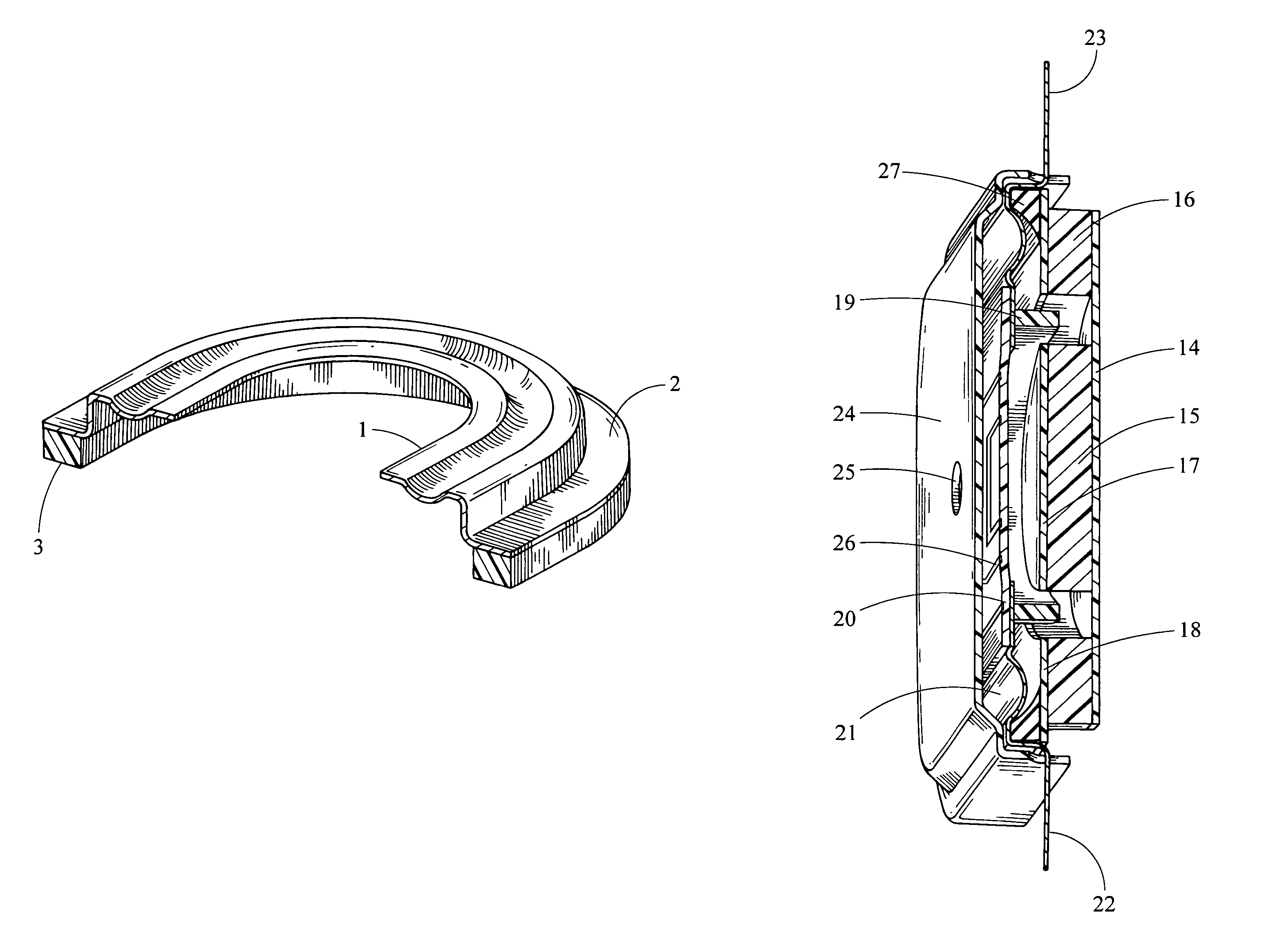
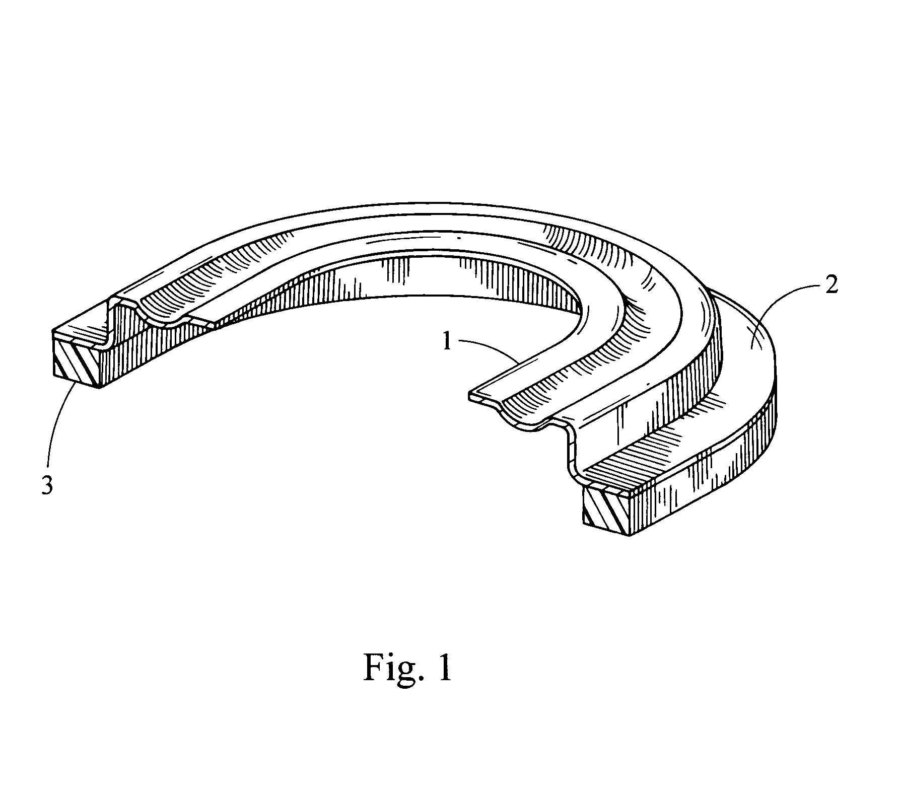
[0047]In its most general aspect the present invention relates to a moulded surround with a build-in mechanical support for simplifying the handling of the surround.

[0048]FIG. 1 shows a first embodiment of the present invention in its most simple form. As seen, FIG. 1 shows a surround having an inner edge 1 and an outer portion 2. The inner edge 1 is adapted for being attached to a piston part (not shown) whereas the outer portion 2 is attached to a support structure 3 for mechanically supporting the surround thereby obtaining an easier handling of the surround. The support structure 3 can be a separate structure which is glued, heated, welded or by other means attached to the outer portion 2. Alternatively, the support structure 3 can form an integral part of the surround in that the support structure 3 can be injection moulded in the same process as the injection moulding of the surround.

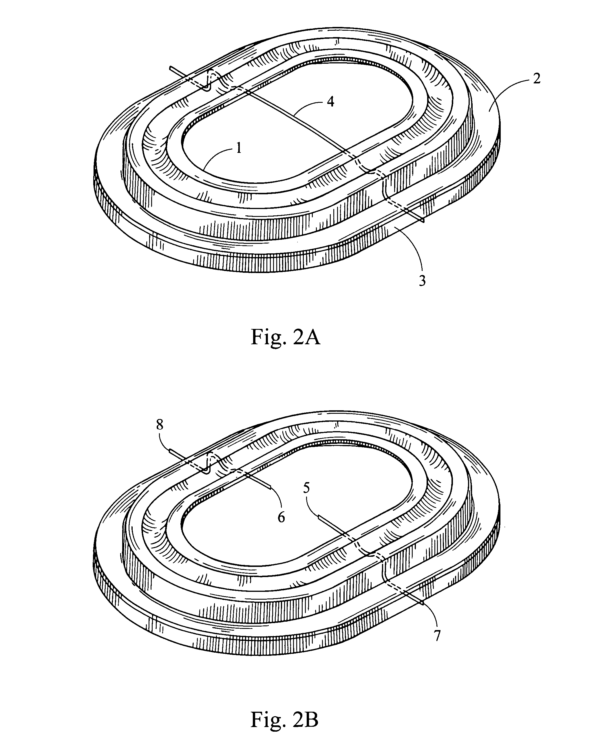
[0049]In FIG. 2a, a through-going integrated lead-out wire 4 is depicted. In FIG. 2b, this thr...


PUM


Abstract

A suspension member for a diaphragm, the suspension member comprising an inner portion being adapted to be attached to a substantially stiff piston part, a outer portion arranged on or integrated with a substantially stiff support member so as to mechanically stabilize the suspension member, and a flexible member connecting the inner and outer portions. The present invention further relates to an electro-acoustic transducer, preferably a miniature electro-acoustic transducer, applying such suspension member.

Description

CROSS-REFERENCE TO RELATED APPLICATION[0001]This application claims the benefit of U.S. Provisional Application Ser. No. 60 / 719,104, entitled “Insert Molded Surround With Mechanical Support,” filed Sep. 21, 2005.FIELD OF THE INVENTION[0002]The present invention relates to a moulded surround with a mechanical support. In particular, the present invention relates to moulded surround of silicone, rubber or any other soft material having a mechanical support attached thereto in order to ease handling of the surround.BACKGROUND OF THE INVENTION[0003]Diaphragms for electro-acoustic transducer typically comprise a substantially stiff piston part and a flexible surround. The piston and flexible surround may be manufactured as a one piece component or they may be manufactured separately. In the latter situation the piston and the surround may be manufactured using different materials. For example, it may be advantageous to manufacture the piston in a stiffer material compared to the material...

Claims


Application Information

Patent Timeline
Patent Type & Authority Patents(United States)
IPC IPC(8): H04R25/00
CPCH04R7/20H04R1/06H04R2307/204H04R2231/003H04R7/02H04R7/18
Inventor ANDERSEN, MORTEN KJELDSENJOHANNSEN, LEIF
Owner SHANDONG GETTOP ACOUSTIC
Why Eureka
Try Eureka