Metal cord and process for manufacturing a metal cord
a technology of metal cords and metal wires, which is applied in the field of metal cords and to a process for manufacturing metal wires, can solve the problems of corrosion, inability to achieve, and inability to achieve, and achieves high elongation at break, high elongation of parts, and improved penetration of elastomeric materials.
Active Publication Date: 2011-07-12
NV BEKAERT SA
View PDF27 Cites 4 Cited by
- Summary
- Abstract
- Description
- Claims
- Application Information
AI Technical Summary
Benefits of technology
[0028]The Applicant has now found a metal cord comprising one or more elementary metal wires, provided with both a high elongation at break and a high part load elongation (PLE), said characteristics being maintained substantially unchanged even after the metal cord has been rubberized and vulcanized. Moreover, said metal cord shows an improved elastomeric material penetration between the adjacent elementary metal wires forming said metal cord.
[0043]Generally, said elementary metal wire is provided with a brass coating (Cu of between 60% and 75% by weight, Zn of between 40% and 25% by weight), having a thickness of between 0.10 μm and 0.50 μm. Said coating ensures better adhesion of the elementary metal wire to the rubberizing compound and provides for protection against corrosion of the metal, both during production of the reinforced elastomeric manufactured articles and during use thereof. Should it be necessary to ensure a greater degree of protection against corrosion, said elementary metal wire may be advantageously provided with an anti-corrosive coating other than brass, able to ensure a greater corrosion resistance, such as, for example, a coating based on zinc, zinc / manganese (ZnMn) alloys, zinc / cobalt (ZnCo) alloys or zinc / cobalt / manganese (ZnCoMn) alloys.
[0058]The preformed metal wire obtained according to step (a) and step (b) is substantially devoid of sharp edges and / or discontinuities in curvature along its longitudinal development. Said feature is particularly advantageous since, the absence of said sharp edges / corners, results in a favourable increasing of the breaking load of the elementary metal wire.
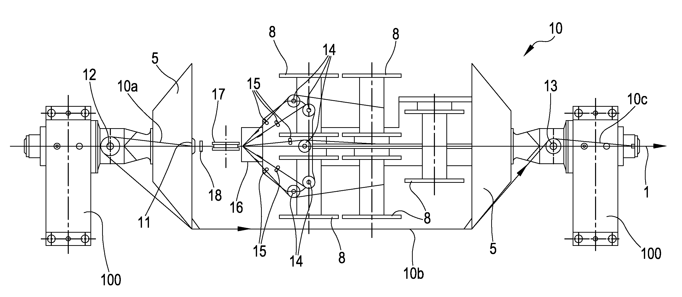
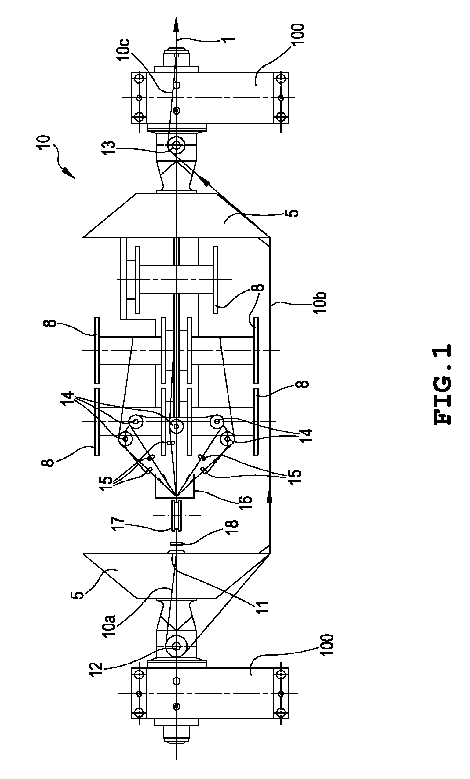
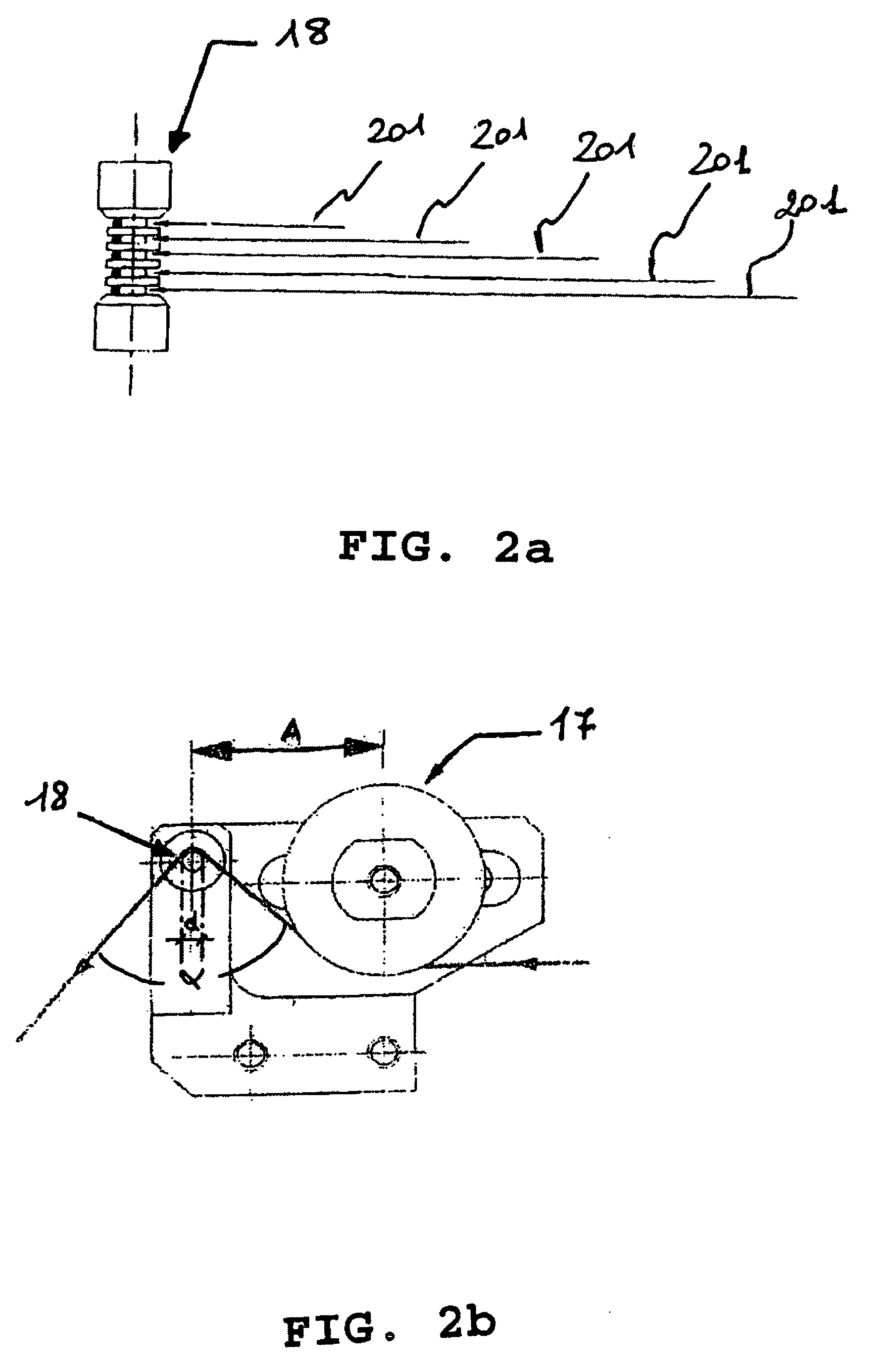
[0065]According to a further preferred embodiment, said at least one first preforming device comprises a first and a second pulley, each pulley having a plurality of circumferentially arranged pins, said pulleys being positioned at a distance so that during rotation the pins of the first and the second pulley interpenetrate so as to induce a substantially sinusoidal deformation without sharp edges on a wire passing through the space between the pins of the first pulley and the corresponding pins of the second pulley.
Problems solved by technology
This result, which is more difficult to be achieved when more complex metal cords are considered, is not easily achieved even when dealing with metal cords formed by a low number of elementary metal wires.
These cavities are closed and, consequently, cannot be reached by the elastomeric material during the normal rubberizing phases of the metal cord and, as a consequence, corrosion may develop inside said closed cavities and propagate along the elementary metal wires forming the same.
As a consequence, this means, for example, that owing to cuts in the reinforced elastomeric manufactured product, humidity and / or external agents may penetrate into said closed cavities inevitably starting a rapid process of corrosion of the elementary metal wires, thus severely compromising the structural resistance of the metal cords themselves and, consequently, of the reinforced elastomeric manufactured product.
Furthermore, the presence of said closed cavities which cannot be reached by the elastomeric material involves a reduced adhesion of the metal wires to the elastomeric material which may cause an undesired tendency of the metal wires to separate from the same.
An additional disadvantage due to insufficient rubberizing of the metal wires, caused by the presence of said closed cavities, is the development of fretting of the metal wires in contact with one another.
This generates an inevitable decrease of resistance to fatigue of the metal wires and, consequently, of the metal cords.
However, the metal cords above disclosed may show some drawbacks.
For example, in the case of the so called “open” cords, the tension to which they are subjected before they reach the rubberizing device, may cause the compacting of the wires one against the other, thus hindering the elastomeric material from penetrating between the adjacent metal wires of the cords.
Consequently, although being endowed with a high part load elongation (PLE), i.e. a high elongation to low load (lower than or equal to 50 N), said cords may not allow a good elastomeric material penetration so causing a corrosion of the metal wires, and severely compromising the structural resistance of both the cords and of the reinforced elastomeric manufactured articles containing the same.
Said low part load elongation (PLE) may cause problems during the manufacturing of the reinforced elastomeric manufactured articles comprising the same, in particular when used in tires manufacturing where remarkable elongations of the metal cords are required during the various manufacturing steps.
Method used
View moreImage
Smart ImageViewing Examples
Examples
examples 1-3
[0097]Three different steel cords having the following characteristics were tested.
example 1
[0098]5×0.25 steel cord wherein all the five elementary steel wires have been double-preformed according to the present invention;
examples 4-5
[0106]Two different steel cords having the following characteristics were tested.
Login to View More PUM
| Property | Measurement | Unit |
|---|---|---|
| Length | aaaaa | aaaaa |
| Length | aaaaa | aaaaa |
| Length | aaaaa | aaaaa |
Abstract
A metal cord includes at least one preformed elementary metal wire. The metal cord has an elongation at break, measured on the bare cord, higher than or equal to 3%, preferably 4% to 6%; an elongation at break, measured on the rubberized and vulcanized cord, which differs in an amount not higher than or equal to 15%, preferably 2% to 10% with respect to the elongation at break measured on the bare cord; a part load elongation, measured on the bare cord, higher than or equal to 0.4%, preferably 0.5% to 1.5%; a part load elongation, measured on the rubberized and vulcanized cord, which differs in an amount not higher than or equal to 15%, preferably 0.5% to 10%, with respect to the part load elongation measured on the bare cord.
Description
CROSS REFERENCE TO RELATED APPLICATION[0001]This application is a national phase application based on PCT / EP2006 / 004353, filed May 10, 2006, the content of which is incorporated herein by reference.BACKGROUND OF THE INVENTION[0002]1. Field of the Invention[0003]This invention relates to a metal cord and to a process for manufacturing a metal cord.[0004]More in particular, the present invention relates to a metal cord, usually used as a reinforcing element in elastomeric manufactured articles, comprising at least one preformed elementary metal wire.[0005]Moreover, the present invention also relates to a process for manufacturing a metal cord.[0006]Furthermore, the present invention also relates to an apparatus for manufacturing a metal cord.[0007]2. Description of the Related Art[0008]The above disclosed metal cord may be employed to produce reinforced elastomeric manufactured articles such as, for example, tires, pipes for high pressure fluids, belts, belt conveyors, and the like.[0...
Claims
Login to View More Application Information
Patent Timeline
 IPC IPC(8): D02G3/02
CPCD07B1/0646D07B7/025D07B2201/2007D07B2201/2022D07B2201/2024Y10T428/12424D07B2201/2039D07B2207/202D07B2501/2046D07B2501/2076Y10T428/12333D07B2201/2029D07B2201/2008
Inventor CRISTOFANI, FABRIZIOCIRILLI, LUCA
Owner NV BEKAERT SA
Features
- R&D
- Intellectual Property
- Life Sciences
- Materials
- Tech Scout
- Unparalleled Data Quality
- Higher Quality Content
- 60% Fewer Hallucinations
Learn More Browse by: Latest US Patents, China's latest patents, Technical Efficacy Thesaurus, Application Domain, Technology Topic, Popular Technical Reports.
© 2025 PatSnap. All rights reserved.Legal|Privacy policy|Modern Slavery Act Transparency Statement|Sitemap|About US| Contact US: help@patsnap.com


