Side tension rails to control bale length variation in a square bale chamber

a technology of side tension rails and bale chambers, applied in baling, agriculture tools and machines, paper/cardboard articles, etc., can solve the problems of inconsistency in bale length and density, and achieve the effect of optimizing the movement of the bale being formed

Active Publication Date: 2011-07-12
BLUE LEAF I P INC
View PDF15 Cites 20 Cited by
  • Summary
  • Abstract
  • Description
  • Claims
  • Application Information

AI Technical Summary

Benefits of technology

[0007]Accordingly, it is an object of the present invention to provide an improved mechanism for controlling bale movement in a bale chamber whereby consistent pressure is applied on all four sides of a bale exiting the baler in order to optimize movement of a bale being formed in the bale chamber.
[0008]It is a further object of the present invention to provide an improved mechanism for controlling the movement of a bale in a bale forming chamber that utilizes contoured guide rails to produce a zone of initially higher resistance to improve initial bale formation thus enabling higher bale density, and a zone of comparatively lower, but consistent resistance to maintain higher bale density and improve bale uniformity.
[0009]It is a further object of the present invention to provide an improved mechanism for controlling guide wall pressure on the bale chamber in a small square baler that incorporates an additional, independently movable pair of guide rails.

Problems solved by technology

The result in many cases is that unequal pressure is exerted on the sides of the bale which results in inconsistent bale length and density.

Method used


Image

  • Side tension rails to control bale length variation in a square bale chamber
  • Side tension rails to control bale length variation in a square bale chamber
  • Side tension rails to control bale length variation in a square bale chamber

Examples


Embodiment Construction

)

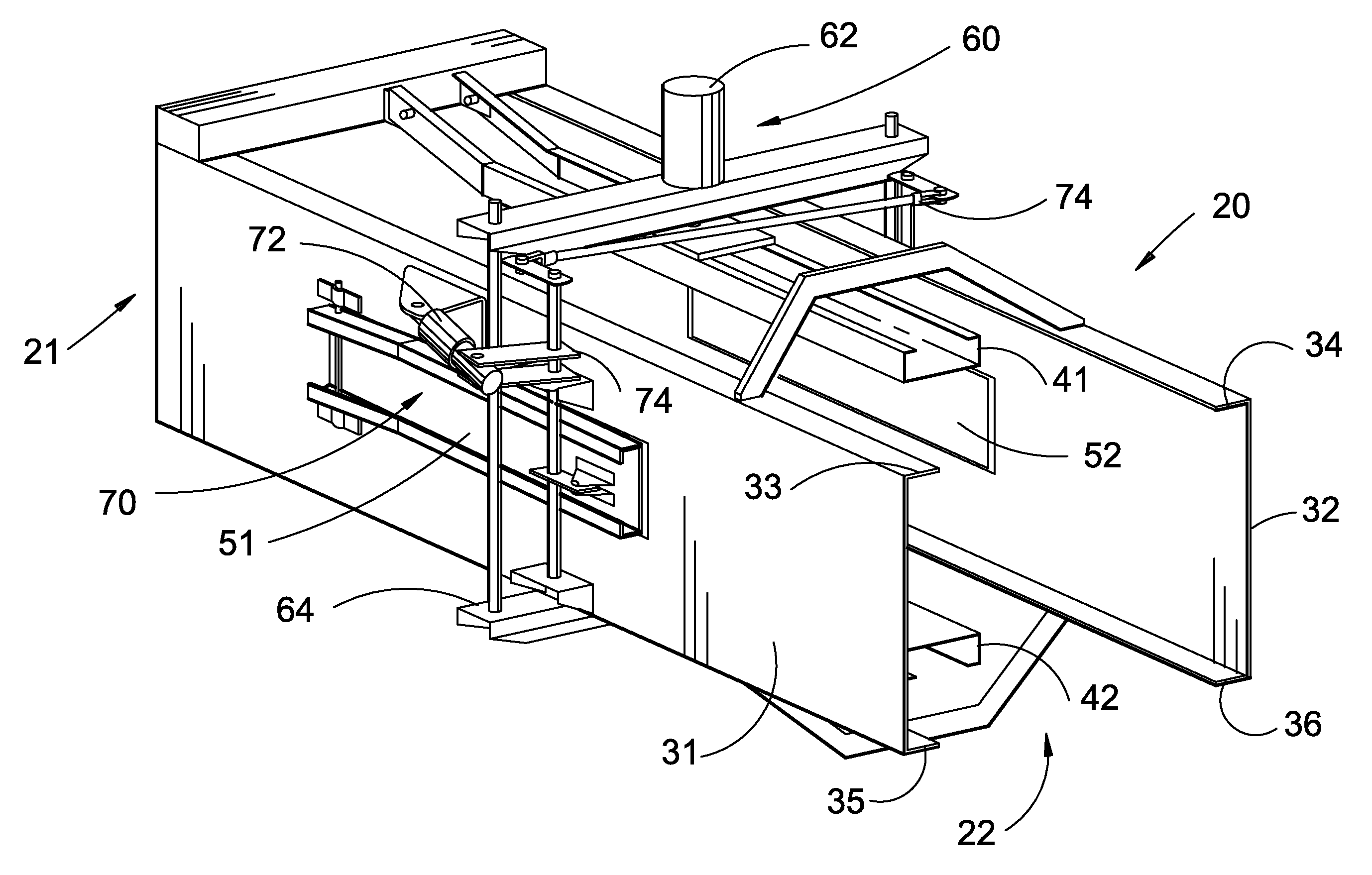
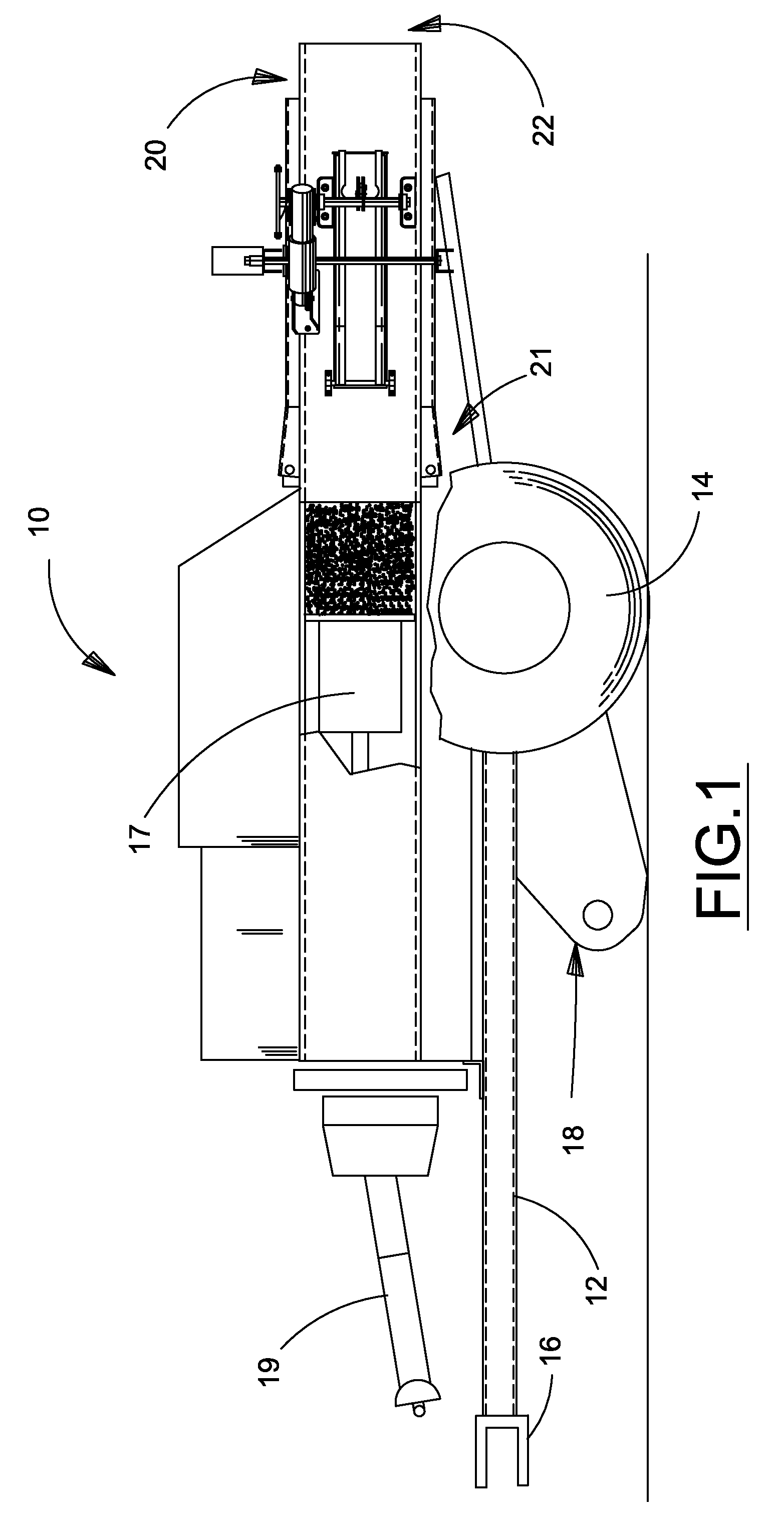
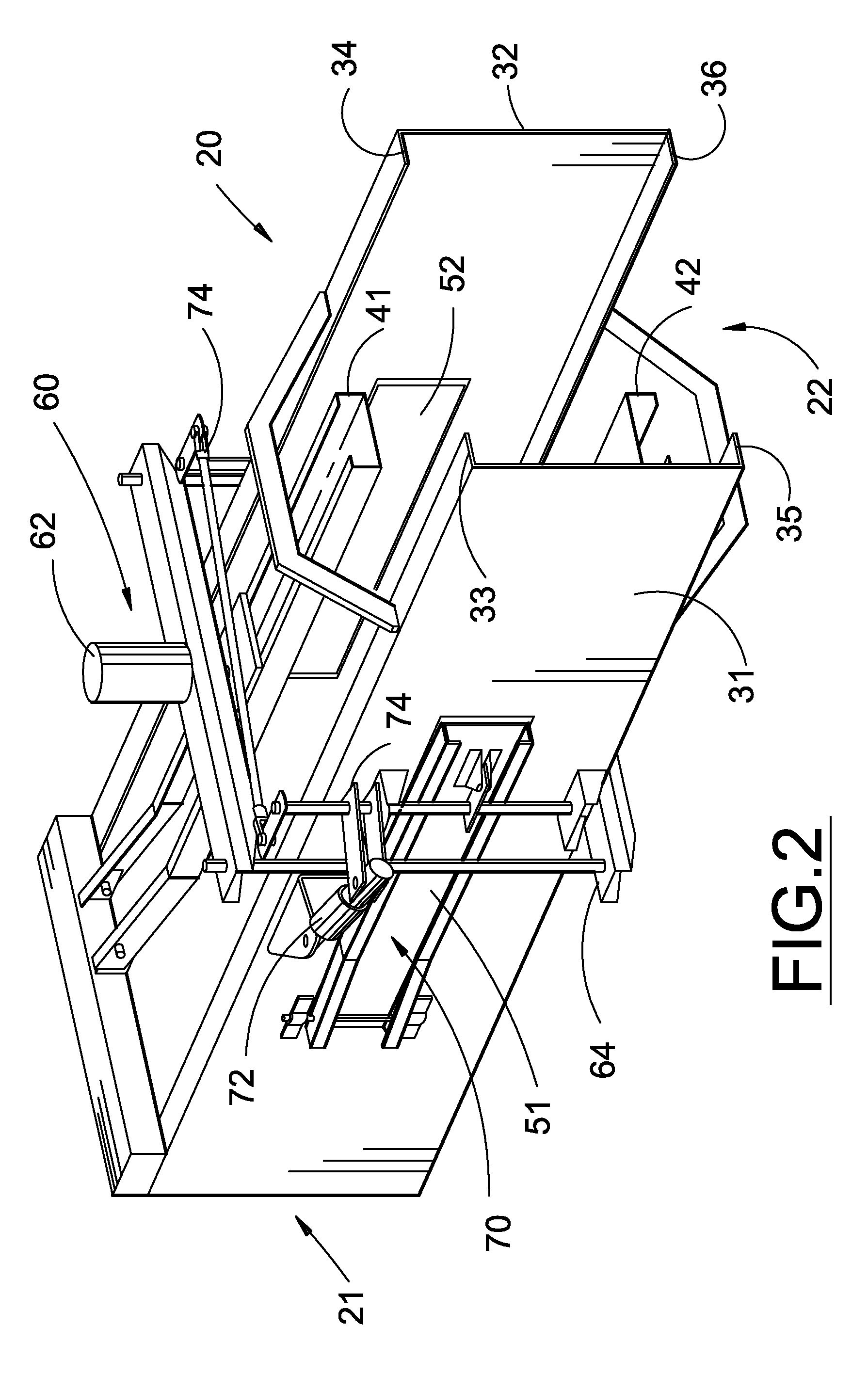
[0022]Many of the fastening, connection, processes and other means and components utilized in this invention are widely known and used in the field of the invention described, and their exact nature or type is not necessary for an understanding and use of the invention by a person skilled in the art, and they will not therefore be discussed in significant detail. Also, any reference herein to the terms “left” or “right,”“up” or “down,” or “top” or “bottom” are used as a matter of mere convenience, and are determined by standing at the rear of the machine facing in its normal direction of travel. Furthermore, the various components shown or described herein for any specific application of this invention can be varied or altered as anticipated by this invention and the practice of a specific application of any element may already be widely known or used in the art by persons skilled in the art and each will likewise not therefore be discussed in significant detail. When referring to ...


PUM


Abstract

An improved mechanism for controlling the pressure applied by the side walls of a square bale chamber comprising two independently positionable opposing pairs of bale tension rails, each pair perpendicularly arranged with respect to each other, whereby a uniform pressure may be exerted on all four sides of the bale in the bale chamber thereby resulting in improved consistency in bale length, density, shape, and appearance.

Description

BACKGROUND OF THE INVENTION[0001]This invention relates generally to agricultural balers of the type commonly referred to as square balers that produce bales having a rectangular cross section, and more particularly to an apparatus for consistently controlling the length of bales produced by small square balers.[0002]Square balers are implements that pick up a swath or windrow of crop material, such as straw or hay, from the ground and deposit it in an infeed housing where it is conveyed by a feed mechanism through an inlet to a bale forming chamber. Four walls define the bale forming chamber where the crop material is urged rearwardly by a reciprocating plunger to form a rectangular package of compacted crop material. The package so formed is automatically tied by a tying mechanism to complete the bale that is then discharged from the chamber by being urged rearwardly by the next bale being successively formed. Completed bales are either deposited on the ground for subsequent retri...

Claims


Application Information

Patent Timeline
Patent Type & Authority Patents(United States)
IPC IPC(8): B30B9/30
CPCA01F15/0825
Inventor HOOVER, LARRY L.JACOBS, STEPHEN W.
Owner BLUE LEAF I P INC
Why Eureka
Try Eureka