Gas fuel tank-equipped vehicle

a fuel tank and gas technology, applied in the field of gas fuel tank equipped vehicles, can solve the problems of difficult flow of gas fuel in the cylinder housing space, inability to discharge gas fuel, etc., and achieve the effects of reducing distance, preventing the turbulent flow of running air, and improving appearan

Active Publication Date: 2011-07-12
TOYOTA JIDOSHA KK
View PDF34 Cites 42 Cited by
  • Summary
  • Abstract
  • Description
  • Claims
  • Application Information

AI Technical Summary

Benefits of technology

[0008]In the gas fuel tank-equipped vehicle, gas fuel filled in the gas fuel tank has a lower specific gravity than air such as CNG (having methane as a main ingredient) or hydrogen. Thus, in the case where the fuel gas leaks from the gas fuel tank due to some circumstances, the fuel gas is lighter than air and thus rises in the tank housing space, immediately reaches a ventilating opening formed in a position above the gas fuel tank in an upper surface of the roof cover, and efficiently flows outside therefrom. This allows fuel gas accumulated in the tank housing space to be discharged at an early stage. The vehicle may include an automobile such as a bus, a large car, or a compact car, or a train.
[0022]In the gas fuel tank-equipped vehicle in which the lower portion of the roof cover is formed to cover the upper portion of the side surface of the vehicle body with the predetermined gap from the side surface, the roof cover includes a pair of cover side surface members formed along right and left side surfaces of the vehicle body, and a cover upper surface member formed in a position one step lower than the highest positions in a vehicle vertical direction of the pair of cover side surface members, and the vent may be formed between the highest position of the cover side surface member and the cover upper surface member. This improves an appearance because the vent is invisible from the outside of the vehicle. This configuration may be adopted alone or in combination with the configuration in which the gap is provided between the lower portion of the roof cover and the side surface of the vehicle body.

Problems solved by technology

However, supposing the case where gas fuel leaks from a gas fuel tank due to some circumstances, the gas fuel accumulated in the cylinder housing space is preferably discharged at an early stage, but in Japanese Patent Laid-Open No. 2000-127860 described above, the gas fuel accumulated in the cylinder housing space is hard to flow when the bus does not run, and the gas fuel cannot be discharged at an early stage.

Method used


Image

  • Gas fuel tank-equipped vehicle
  • Gas fuel tank-equipped vehicle
  • Gas fuel tank-equipped vehicle

Examples


Embodiment Construction

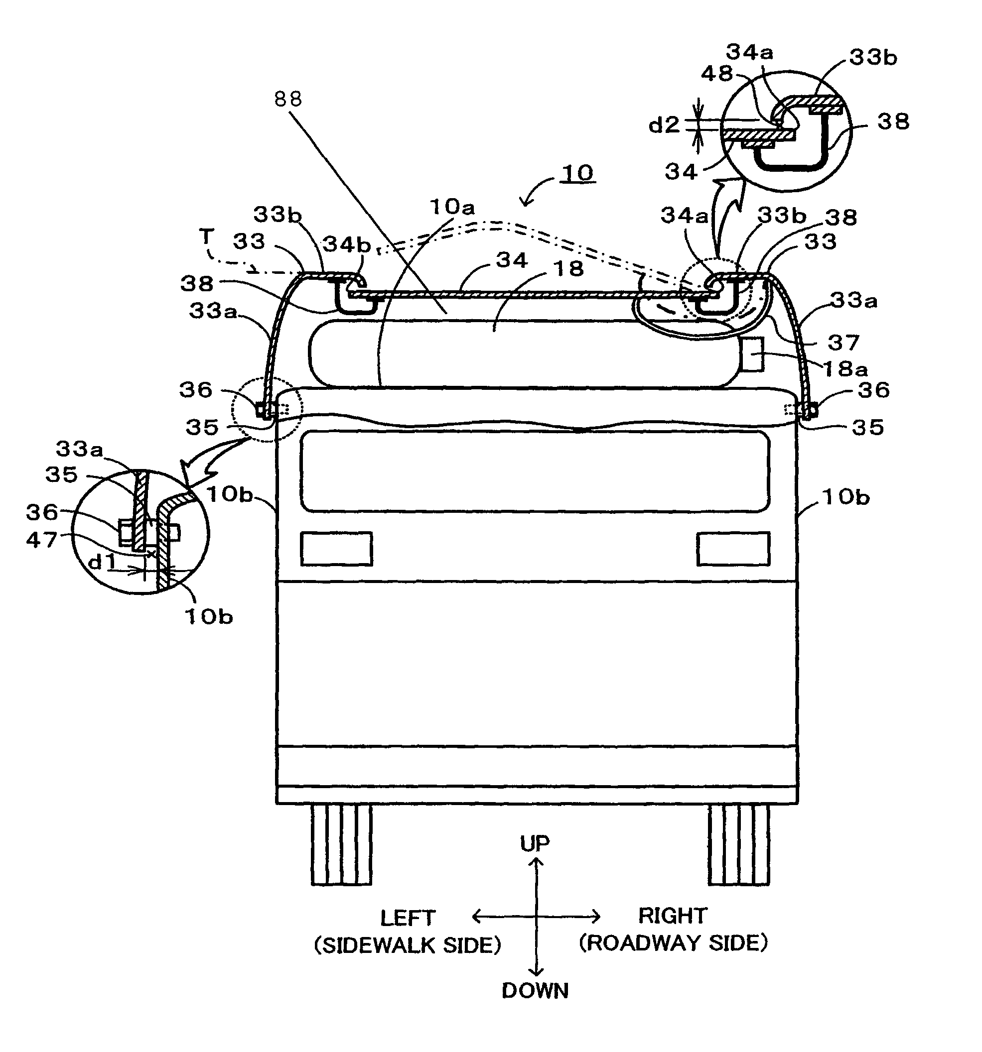
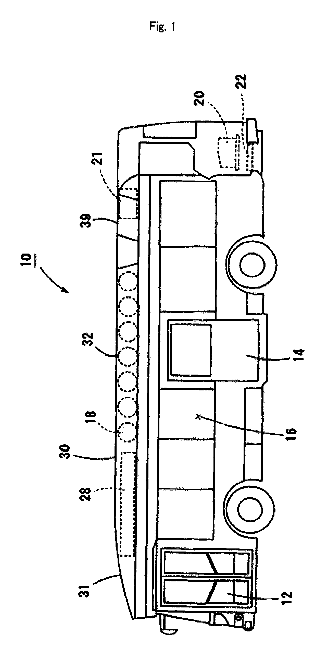
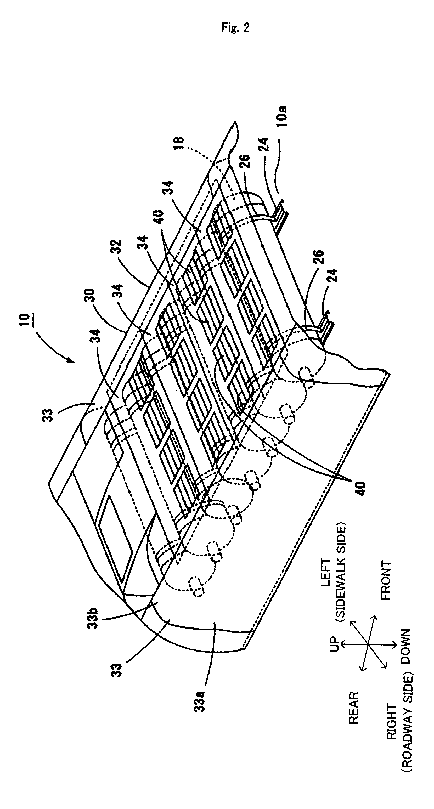
[0031]Now, the best mode for carrying out the present invention will be described with reference to the drawings. FIG. 1 is a left side view of a fuel cell-equipped bus 10, FIG. 2 is a perspective view of an upper portion of the fuel cell-equipped bus 10, FIG. 3 is a back view (cross-sectional view) of the fuel cell-equipped bus 10, and FIG. 4 is a perspective view of a cover middle upper surface member 34.

[0032]As shown in FIG. 1, the fuel cell-equipped bus 10 of the embodiment is configured as a large low-floor bus including a front platform 12 provided in the front in a left side surface and a middle platform 14 provided in the middle in the left side surface, through which passengers are loaded into and unloaded from a passenger compartment 16, and includes no platform in a right side surface of the vehicle. The fuel cell-equipped bus 10 includes seven hydrogen cylinders 18 as gas fuel tanks in an upper portion thereof, and a fuel cell stack 20 constituted by stacked several hun...


PUM


Abstract

Hydrogen leaking from a hydrogen cylinder has a lower specific gravity than air, thus rises in a cylinder housing space, and reaches a ventilating opening constituted by a group of slits formed in an upper surface of a roof cover. At this time, the ventilating opening is formed in a position above the hydrogen cylinder, and thus the leaking hydrogen can reach the ventilating opening in a short distance as compared with the case where the ventilating opening is formed in a position apart from the position above the hydrogen cylinder. The ventilating openings are provided in a plurality of locations, and thus the leaking hydrogen reaches the closest ventilating opening. The hydrogen gas reaches the ventilating opening, passes upward therethrough and flows outside.

Description

[0001]This is a 371 national phase application of PCT / JP2006 / 300107 filed 6 Jan. 2006, which claims priority to Japanese Patent Applications No. 2005-002270 & No. 2005-002272, both filed 7 Jan. 2005, the contents of which are incorporated herein by reference.TECHNICAL FIELD[0002]The present invention relates to a gas fuel tank-equipped vehicle.BACKGROUND ART[0003]In recent years, a low-emission vehicle has been known to which a gas fuel tank filled with high pressure gas fuel is mounted. For example, Japanese Patent Laid-Open No. 2000-127860 discloses a bus to which a CNG cylinder filled with compression natural gas (CNG) as gas fuel is mounted. This bus is such that a roof cover that covers a roof forms a cylinder housing space that houses the CNG cylinder, and a gap is provided between a lower edge of a front surface of the roof cover and the roof. When the bus runs, air flows into the cylinder housing space through the gap, and the air having passed through the cylinder housing s...

Claims


Application Information

Patent Timeline
Patent Type & Authority Patents(United States)
IPC IPC(8): B60P3/22
CPCB60H1/00371B60K15/07B62D25/06B60H2001/00235B60Y2200/143B60K2015/0639B60Y2200/1432
Inventor NAGANUMA, YOSHIAKIISHIKAWA, NORIMASA
Owner TOYOTA JIDOSHA KK
Why Eureka
Try Eureka