Exoskeleton robot system and kinematics extremity detection-based control method

A technology of exoskeleton robot and driving system, which can be applied in the direction of equipment to help people walk, physical therapy, etc. It can solve the problems of poor human-computer interaction performance, no effective control method, and difficulty in achieving control effects. The effect of reducing the bearing capacity and reducing the gravity

Active Publication Date: 2014-12-24
HARBIN INST OF TECH
View PDF8 Cites 42 Cited by
  • Summary
  • Abstract
  • Description
  • Claims
  • Application Information

AI Technical Summary

Problems solved by technology

[0004] The present invention is to solve the problem that the traditional electromyographic signal detection method assists in improving human walking, and it is difficult to achieve accurate control effects. In the process of assisting human walking to resist its own gravity, the human-computer interaction performance is poor, and there is no effective control method. problem, and then provide an exoskeleton robot system and a control method based on kinematics end detection

Method used


Image

  • Exoskeleton robot system and kinematics extremity detection-based control method
  • Exoskeleton robot system and kinematics extremity detection-based control method
  • Exoskeleton robot system and kinematics extremity detection-based control method

Examples


specific Embodiment approach 1

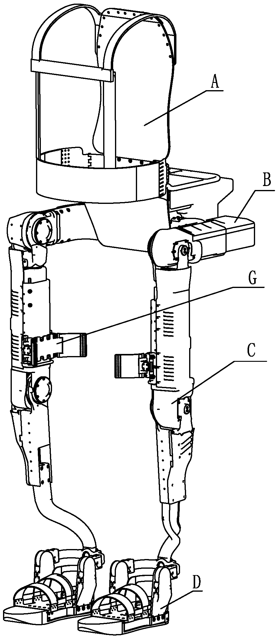
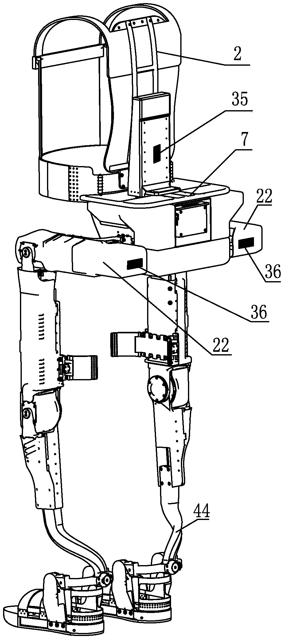
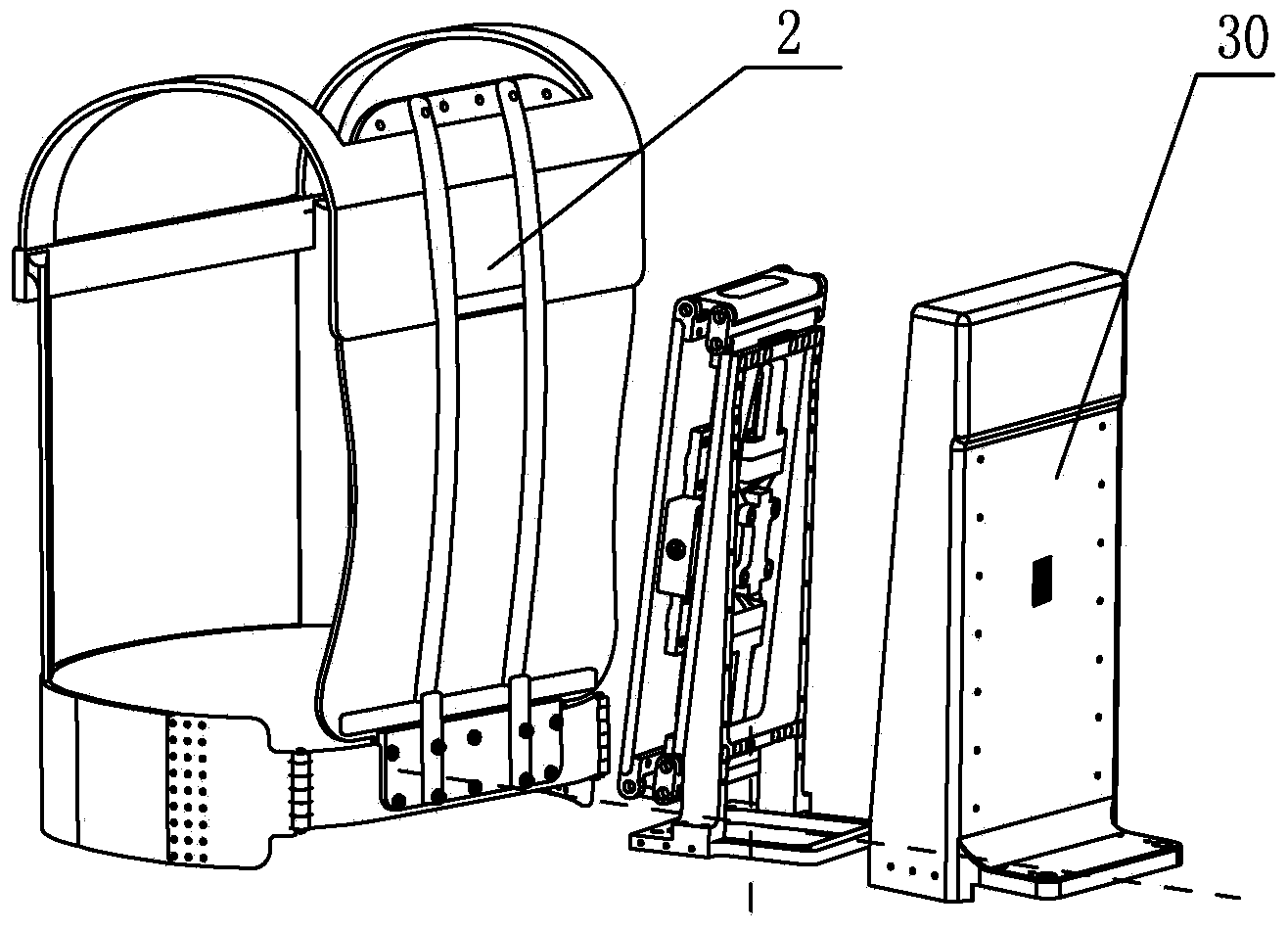
[0038] Specific implementation mode one: combine Figure 1-Figure 7 and Figure 11 Explain that an exoskeleton robot system in this embodiment includes an upper body back A, a left leg and a right leg, and the left leg and the right leg respectively include a hip driving system B, a knee driving system C, a foot wearing system D and Binding device G; the back of the upper body A includes a human body back support 2 and a load mounting plate 7, the human body back support 2 is installed on the load mounting plate 7, the hip driving system B includes a shell 22, and the knee driving system C includes a calf Connecting plate 44, foot wearing system D comprises U-shaped connecting plate 51, foot rubber sole 58 and two vertical lugs 55-2, the middle part of U-shaped connecting plate 51 is hinged with the lower end of shank connecting plate 44, U-shaped The two ends of the connecting plate 51 are respectively rotatably connected with the two vertical lugs 55-2;

[0039] It also in...

specific Embodiment approach 2

[0051] Specific implementation mode two: combination Figure 6 Explain that one end of the first cantilever beam 19 in this embodiment is processed with a spherical portion, one end of the second cantilever beam 20 is processed with a spherical portion, and the spherical portion of the first cantilever beam 19 is inserted into one of the grooved support plates 10 In the opening of the second cantilever beam 20 , the spherical portion is inserted into the opening of the remaining one trough-shaped support plate 10 . In this way, in the force information transmission of the cantilever beam, a spherical force transmission configuration structure is designed, which reduces the friction loss and improves the detection sensitivity. Others are the same as in the first embodiment.

specific Embodiment approach 3

[0052] Specific implementation mode three: combination Figure 7 Note that each of the strain gauges 25 in this embodiment is a foil resistance strain gauge or a strain gauge sensor. Such a setting, such a setting, has a wide measurement range, good product stability, high sensitivity, and can measure a variety of mechanical signals. Others are the same as in the first or second embodiment.


PUM


Abstract

The invention discloses an exoskeleton robot system and a kinematics extremity detection-based control method, and relates to an exoskeleton robot system and a control method to solve the problems that an accurate control effect cannot be achieved by the traditional electromyographic signal detection method for assisting in improving the walk of a human body, and man-machine interaction performance is low and an effective control method is lacked in the aspect of resisting self weight in the process of assisting in doing walk of the human body. The exoskeleton robot system comprises an upper body back, a left leg and a right leg; the left leg and the right leg respectively comprise a hip driving system, a knee driving system, a foot wearing system and a binding device; the exoskeleton robot system also comprises insole plates, a back detection shell, a nine-axis flight attitude measurement module, an industrial control computer, two thin film pressure sensors, two first angle sensors, two second angle sensors, two three-axis inclination sensors and three sets of three-dimensional contact force detection device. The exoskeleton robot system and the method are used for assisting in walking and performing detection and control of a moving posture of the human body.

Description

technical field [0001] The invention relates to an exoskeleton robot system and a control method. Background technique [0002] Wearable exoskeleton has gradually become a research hotspot in the field of robotics. It can help the body bear weight and enhance the ability of exercise. In terms of walking with heavy loads, there are many control methods in the field of exoskeleton research to realize this function. However, in assisting the human body to walk against its own gravity, there is no effective control method. However, the latter is of great significance for the application of assisting the walking of the elderly. With the development of population aging, more and more elderly people are facing difficulties in daily life and mobility. The decline in muscle strength makes it difficult to walk like a healthy person. Therefore, there is a need for an exoskeleton control technology that can help the elderly to bear their own weight after wearing it, so that the mus...

Claims


Application Information

Patent Timeline
Patent Type & Authority Applications(China)
IPC IPC(8): A61H3/00
Inventor 朱延河赵杰张超
Owner HARBIN INST OF TECH
Why Eureka
Try Eureka