Device and method for knee ligament strain measurement

a technology of knee ligaments and devices, applied in the field of knee ligament strain measurement, can solve the problems of unreproducible damage to the anterior and/or posterior cruciate ligaments, the capsule of the knee, and the inability to analyze knee stability, so as to achieve the effect of high repeatability and precision

Inactive Publication Date: 2011-07-12
MAYR HERMANN
View PDF11 Cites 8 Cited by
  • Summary
  • Abstract
  • Description
  • Claims
  • Application Information

AI Technical Summary

Benefits of technology

[0005]It is a general object of the present invention to provide a system and a method for testing the condition of knee ligaments that provides an objective measurement of displacement between the proximate tibia and the distal femur with higher repeatability and precision.
[0023]To increase stability and reproducibility, preferably the foot 42 is fixed onto a foot support platform 30, preferably by a side frame 31 and / or by straps 32 like Velcro straps. Preferably fixing the foot 42 on the foot support platform 30 is done with a natural position of the foot. Furthermore, it is preferred that the knee 44 is held in a predetermined position, specifically resulting in a predetermined angle between the femur axis 47 and the tibia axis 48. This can be done by a thigh support platform 51 which is placed under the knee 44 of the patient lying on the examining table 50. Further stabilization of the knee may be performed by additional side stops 65 which may be pressed by a predetermined force against the knee to either the medial or the lateral side or both sides. The force is preferably in a range between 1 N and 15 N.

Problems solved by technology

When exercising sports, damage to the anterior and / or posterior cruciate ligament and the capsule of the knee is a common consequence of trauma of the knee.
The results are rather unreproducible owing to varying positions and varying force applied to the knee.
This device does still not allow analysis of knee stability in internal and external rotation of the lower leg.
Furthermore, it is susceptible to slightly varying positions of the patient, specifically because the tibia is not exactly fixed.
This device suffers from the same problem as the device mentioned previously.

Method used


Image

  • Device and method for knee ligament strain measurement
  • Device and method for knee ligament strain measurement
  • Device and method for knee ligament strain measurement

Examples


Embodiment Construction

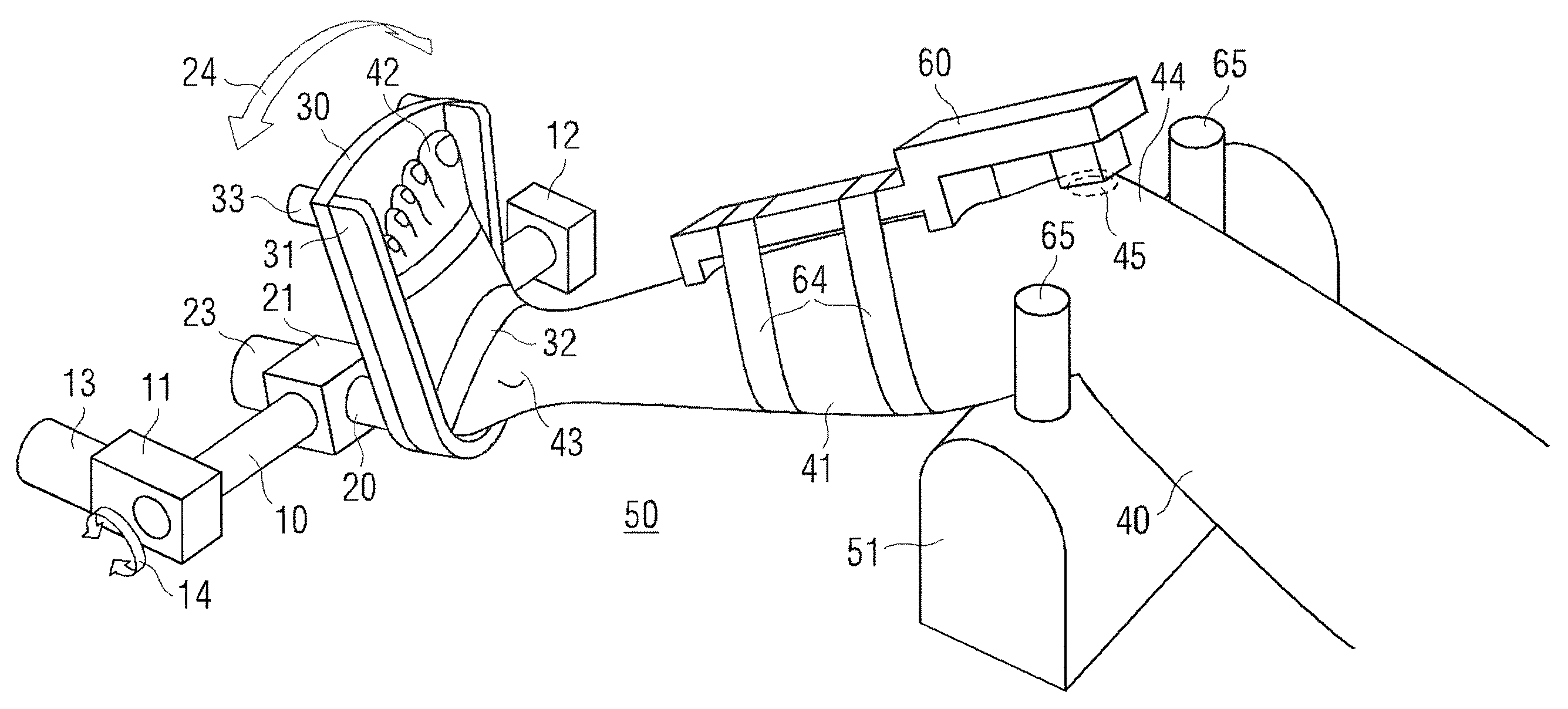
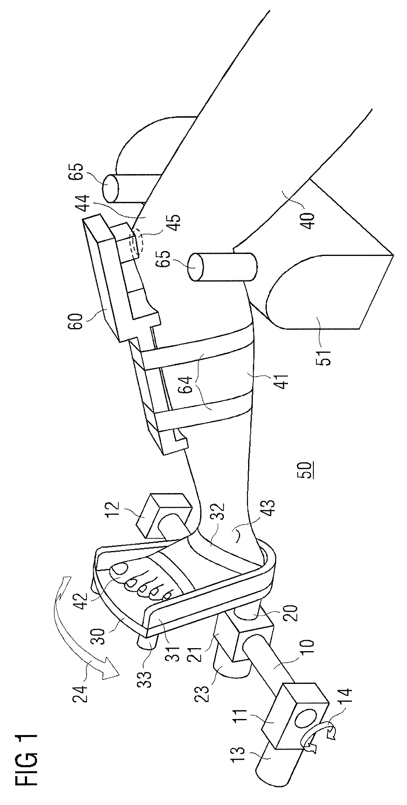
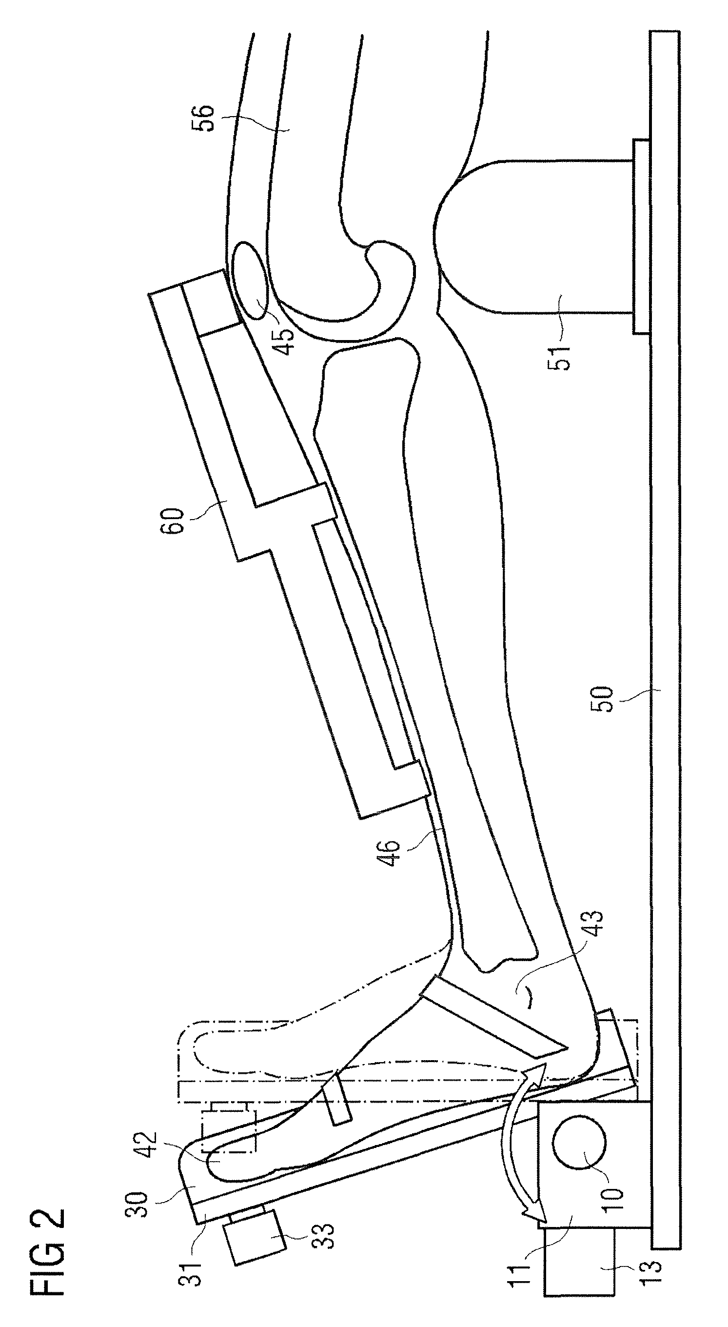
[0043]Referring to FIG. 1, the lower leg of the patient lying on the examining table 50 is shown. It comprises thigh 40, shank 41 and ankle 43. The knee 44 is supported by a thigh support platform 51. The foot 42 is positioned into a foot support platform 30 and fixed therein by a frame 31 which may be adjusted to the size of the foot by adjustment means 33. In addition, straps like Velcro straps 32 may be used to secure the foot on the foot support platform. Furthermore, additional straps 64 like Velcro straps may be used to secure the knee against the thigh support platform 51. Furthermore, the thigh support platform may have additional side stops 65 to prevent lateral movement of the knee.

[0044]The foot support platform 30 is mounted tiltable about at least two axes relative to the examining table 50. A tilt movement 14 of the foot support platform 30 around the first axis can be performed by rotation of a first shaft 10. This first shaft 10 is held by means of the bearings 11 an...


PUM


Abstract

A device for measuring displacement of the tibia in relation to the femur in response to an applied force or torque on the tibia. A first shaft is tiltable about a first axis close to the ankle and approximately parallel to the coronal plane of the patient's body. A second shaft is connected to the first shaft and is rotatable about a second axis perpendicular to the first axis, and is close to the ankle and approximately parallel to the tibia. A foot support platform is mounted on the second shaft, the foot support platform being configured for attachment of the foot at a fixed position. A displacement test device is provided for applying forces to the tibia and measuring the shift or displacement of the proximal tibia relative to the distal femur.

Description

FIELD OF THE INVENTION[0001]The invention relates to a medical device and a method for measuring displacement of the proximal tibia relative to the distal femur as a result of applied forces.DESCRIPTION OF THE PRIOR ART[0002]When exercising sports, damage to the anterior and / or posterior cruciate ligament and the capsule of the knee is a common consequence of trauma of the knee. Various methods are known for analyzing the status of the knee. A manual test which can be performed by an orthopedic surgeon is the Lachman test. The results are rather unreproducible owing to varying positions and varying force applied to the knee. Especially if performed by different persons, for example for comparing the pre- and postoperative status, the results are hardly comparable.[0003]In the U.S. Pat. No. 4,583,555 a device for controlled measurement is disclosed. With this device the surgeon can apply a predetermined force to the tibia and measure the displacement between the femur and the tibia. ...

Claims


Application Information

Patent Timeline
Patent Type & Authority Patents(United States)
IPC IPC(8): A61B5/117A61B5/103
CPCA61B5/1071A61B5/1121A61B5/1124A61B5/4533A61B5/6828A61B5/702A61H1/024A61B5/6829A61B5/6831
Inventor MAYR, HERMANN
Owner MAYR HERMANN
Why Eureka
Try Eureka