Method for passive seismic emission tomography including polarization correction for source mechanism
- Summary
- Abstract
- Description
- Claims
- Application Information
AI Technical Summary
Benefits of technology
Problems solved by technology
Method used
Image
Examples
Embodiment Construction
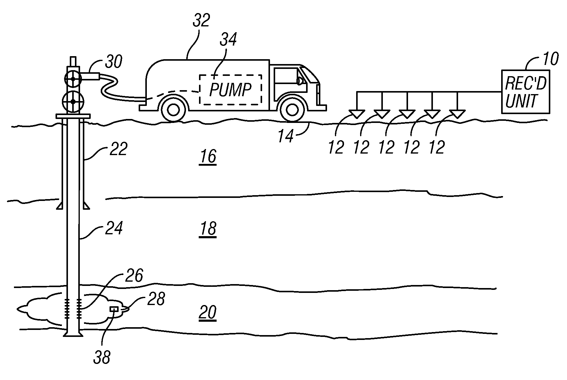
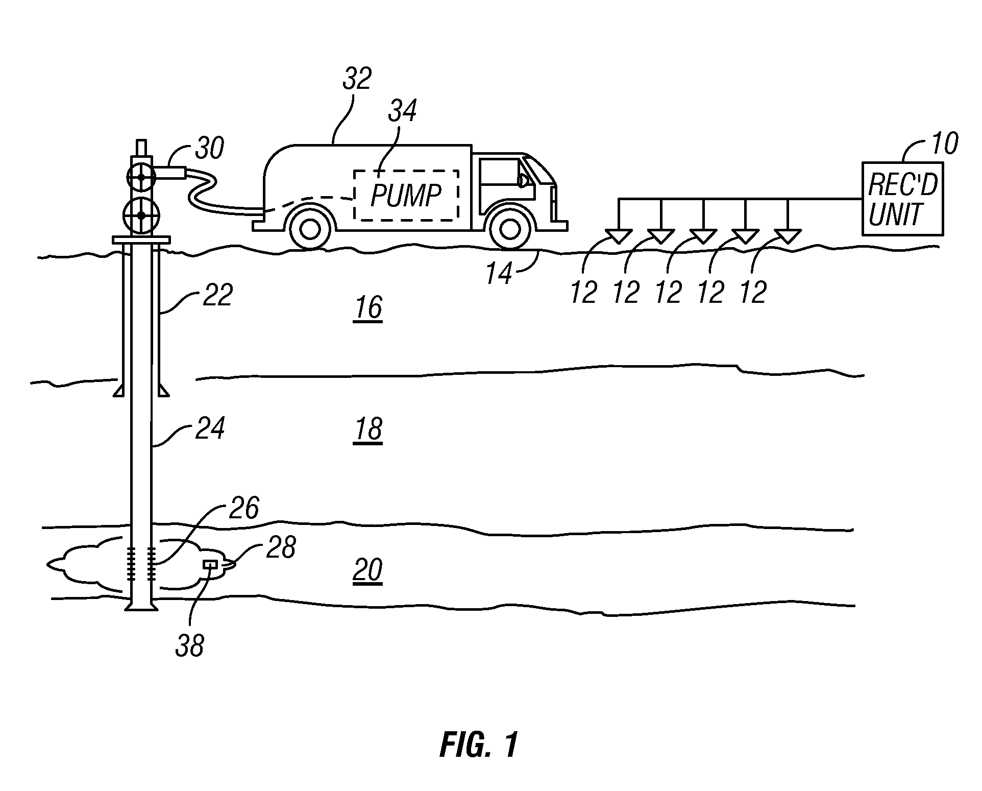
[0019]FIG. 1 shows a typical arrangement of seismic sensors as they would be used in one application of a method according to the invention. The embodiment illustrated in FIG. 1 is associated with an application for passive seismic emission tomography known as “fracture monitoring.” It should be clearly understood that the application illustrated in FIG. 1 is only one possible application of a method according to the invention.
[0020]In FIG. 1, each of a plurality of seismic sensors, shown generally at 12, is deployed at a selected position proximate the Earth's surface 14. In marine applications, the seismic sensors would typically be deployed on the water bottom in a device known as an “ocean bottom cable.” The seismic sensors 12 in the present embodiment may be geophones, but may also be accelerometers or any other sensing device known in the art that is responsive to velocity, acceleration or motion of the particles of the Earth proximate the sensor. The seismic sensors 12 genera...
PUM
 Abstract
Description
Claims
Application Information
 - R&D
- Intellectual Property
- Life Sciences
- Materials
- Tech Scout
- Unparalleled Data Quality
- Higher Quality Content
- 60% Fewer Hallucinations
Browse by: Latest US Patents, China's latest patents, Technical Efficacy Thesaurus, Application Domain, Technology Topic, Popular Technical Reports.
© 2025 PatSnap. All rights reserved.Legal|Privacy policy|Modern Slavery Act Transparency Statement|Sitemap|About US| Contact US: help@patsnap.com


