Driver circuit for loads such as LED, OLED or LASER diodes

a technology of driving circuit and load, which is applied in the direction of lasers, semiconductor lamp usage, electroluminescent light sources, etc., can solve the problems of high loss, limited dynamic behavior, and high efficiency of switching converters

Active Publication Date: 2011-07-12
SIGNIFY HLDG BV
View PDF14 Cites 14 Cited by
  • Summary
  • Abstract
  • Description
  • Claims
  • Application Information

AI Technical Summary

Benefits of technology

[0016]A circuit according to the invention provides great flexibility in obtaining a load current in accordance with the set current value. From the outside, the driver circuit only needs the provided set current value. The microcontroller takes care of providing, for each state of operation, the corresponding control for the two elements, namely the switching converter and the linear current driver. The combination of these two allows to benefit both from the excellent dynamic properties of the linear current driver, and from the reduce losses at the switching converter. Still, external control of the circuit is very easy.
[0019]One of the preferred embodiments relates to control within the steady portions. Here, during at least a part of the steady portions (preferably a central part, i.e. not directly bordering on a change portion), control is effected to minimize a voltage over the linear current driver. This is due to the fact that the linear current driver, if it effectively limits the load current by increasing the voltage drop at the amplification element, introduces high losses. While such losses may be tolerated for a short time, e.g. within the change portions and in limited time periods before and / or after, they should be minimized over a long term. Thus, minimizing the voltage drop over the linear current driver will significantly limit these losses. Preferably, however, minimization is performed such that a lower limit value (minimum threshold value) for the voltage is maintained, allowing the linear current driver to still operate within its linear range. This control behavior is achieved by the corresponding control program. Preferably, as will be further explained with relation to preferred embodiments, the minimum threshold value may be calculated such that a minimum voltage remains for operation of the amplification element within the linear current driver. The minimum threshold value may thus be calculated dependent on the load current. Alternatively, it is possible to determine a fixed value for the minimum threshold value, and to store this value in (or make it accessible to) the control means.
[0022]While this is also true for changes where the set current value decreases in the change portion, it is especially applied for change portion during which the set current value rises. If, for example in a pulse application, the set current value rises and then remains constant in a following steady portion, the control program may provide a higher desired switching output voltage before and during the change portion so that e.g. an output capacitor is charged and the linear current driver may operate in the linear range also for the higher set current value. Then, within the steady portion, (at least during a later part of the steady portion) the desired output switching value is again lowered, as described above, to limit losses in the linear current driver.
[0024]The storage means may be pre-programmed with predetermined values. According to a further preferred embodiment, however, it is preferred to have the program store values determined during control. It is further preferred to use the stored values during control as starting values only, and determine appropriate values by subsequent closed-loop control. The thus given values then may be stored in the storage means to update previous values. In this way, the storage is always kept updated, such that any changes in the driving circuit and / or the load may be compensated.
[0026]While for the plurality of branches there is only one switching converter, each branch has an individual linear current driver circuit connected in series to the terminal. Also, there is an individual sensing input in each of the branches. Accordingly, the control unit will have (direct or multiplexed) input terminals for the sensing input from each of the branches. In this way, multiple loads can be very effectively driven by a circuit with low part count, where only one switching converter and only one control unit with microcontroller is used for a plurality of loads. There may be any number, such as 2, 3 or more loads connected. The loads may be driven simultaneously, but for some applications—such as sequential color rendering in projection applications—it is preferred to drive the loads sequentially.

Problems solved by technology

Linear current drivers can be designed to have the advantage of an excellent dynamic behavior, but are known to introduce high losses.
Switching converters are known for high efficiency, but have limited dynamic behavior.

Method used


Image

  • Driver circuit for loads such as LED, OLED or LASER diodes
  • Driver circuit for loads such as LED, OLED or LASER diodes
  • Driver circuit for loads such as LED, OLED or LASER diodes

Examples


Embodiment Construction

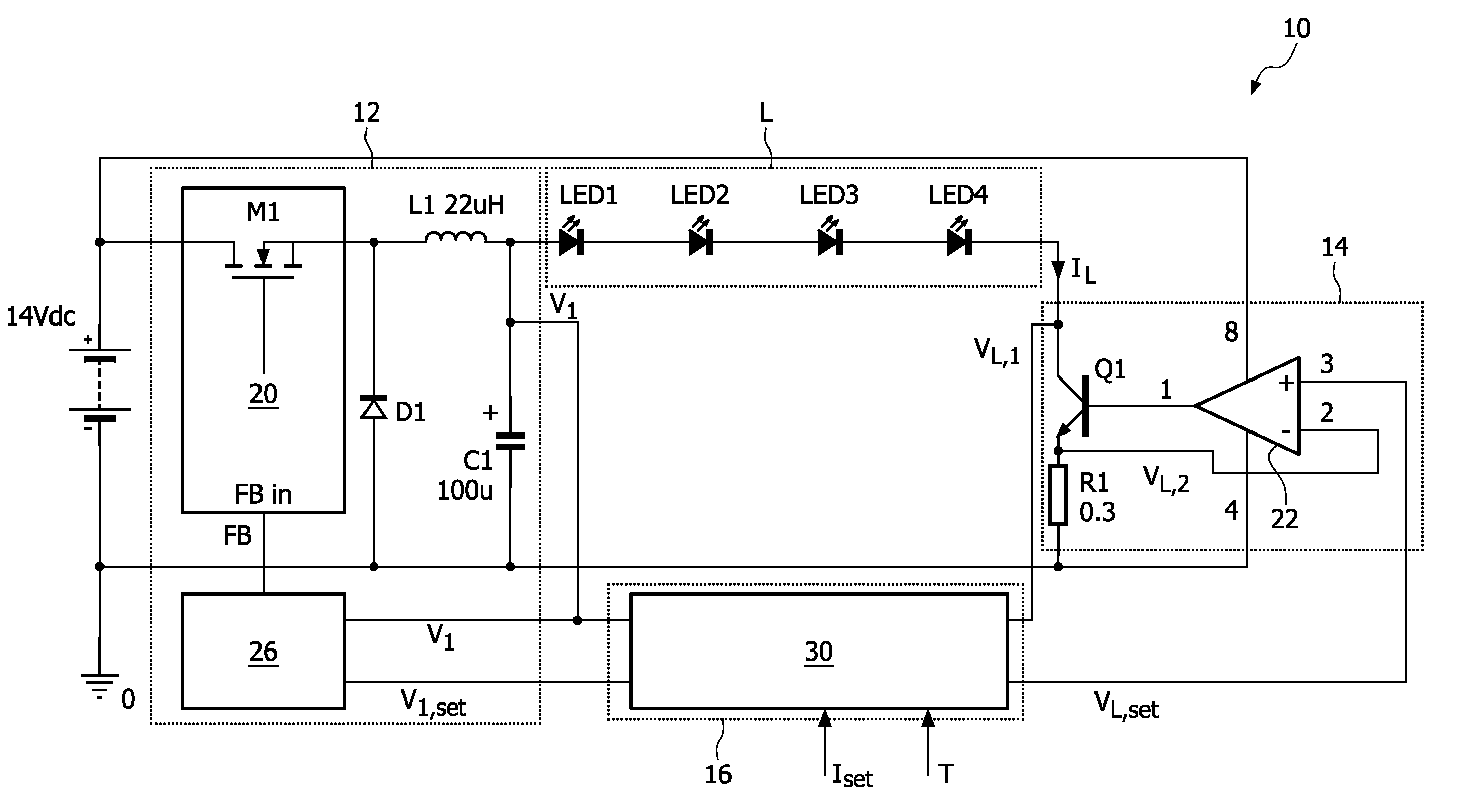
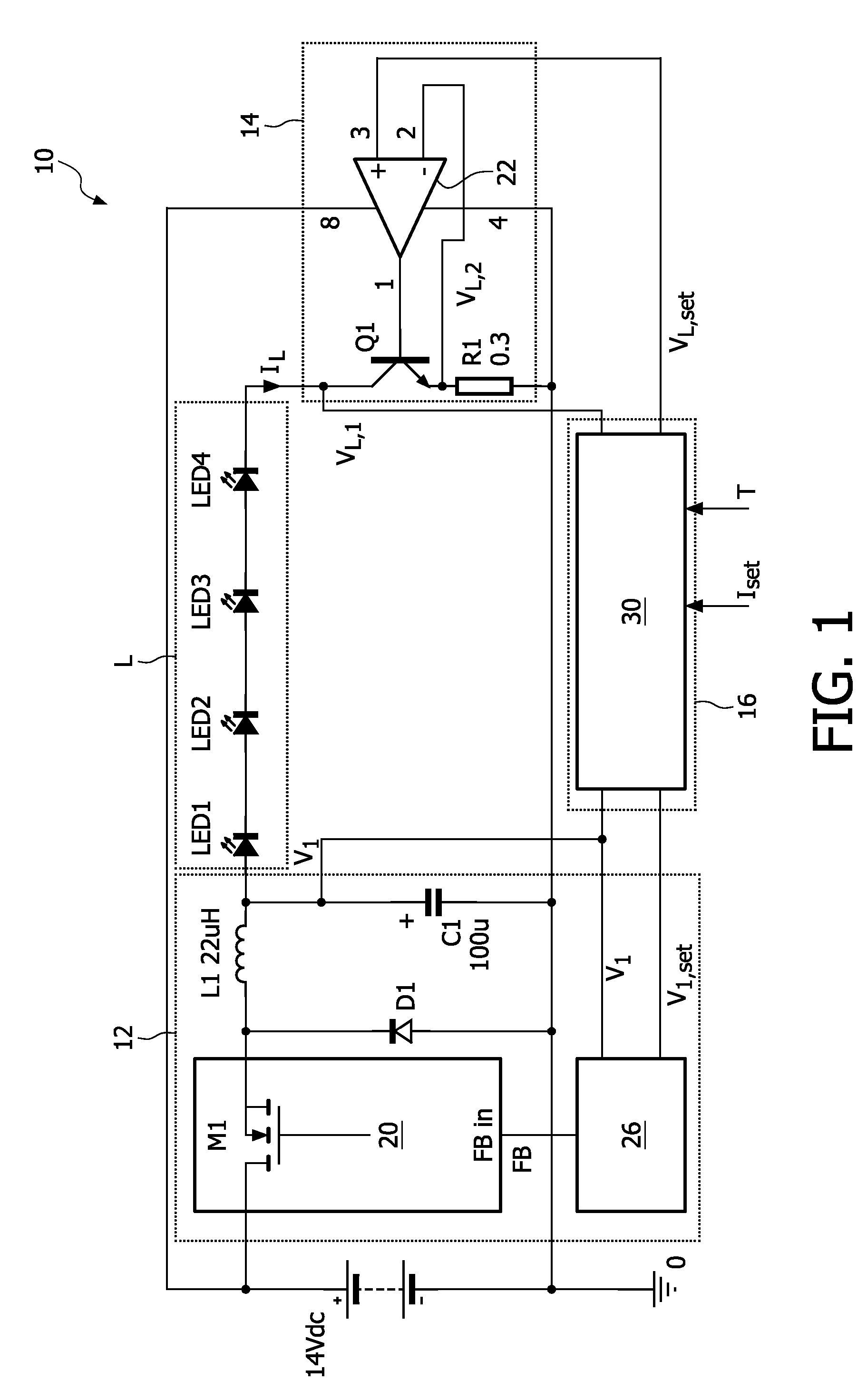
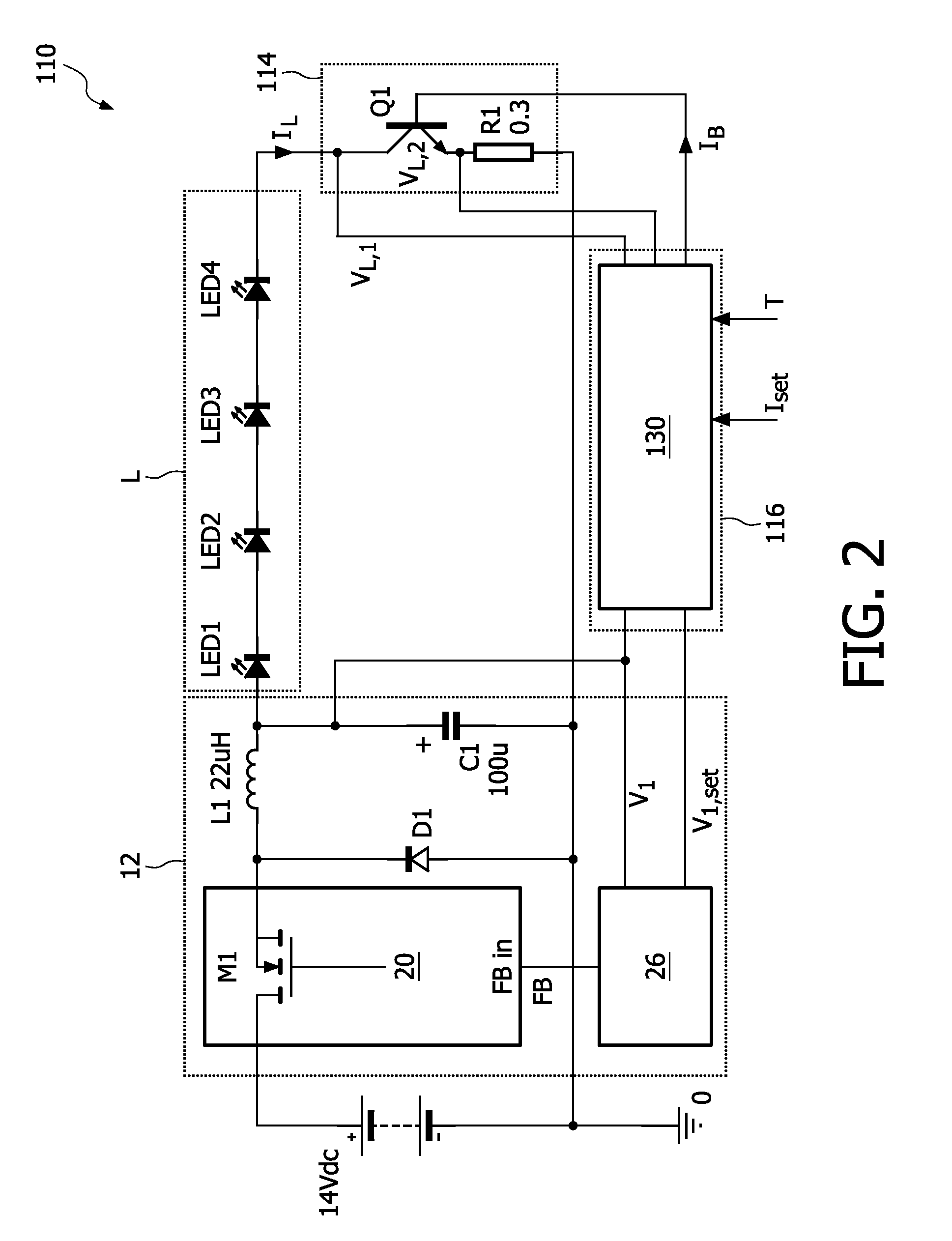
[0036]FIG. 1 shows a circuit diagram of a driver circuit 10 connected to a load L.

[0037]In the example shown, the load L is an LED load, in this case a series of four LEDs LED1, LED2, LED3, LED4. As will become apparent, the driver circuit 10 may alternatively be used to drive other devices, especially light-emitting devices such as OLED or LASER diode devices. It is easily recognizable for the skilled person how to connect other devices to the driver circuit 10.

[0038]The driver circuit 10 comprises a switching converter 12, a linear current driver 14 and a control unit 16. The switching converter 12 supplies a switching output voltage V1. The load L and the linear current driver 14 are connected in series to the output V1. The control unit 16 receives a set value Iset indicating the desired current for the operation of the load L. The control unit 16 drives the components 12, 14 of the driver circuit 10 to achieve a load current. I2 which as closely as possible follows Iset.

[0039]T...


PUM


Abstract

A driver circuit for driving loads such as LED, OLED or LASER diode devices includes a switching converter that has a switching element and reactive elements to provide an output switching voltage by sequential switching operations of the switching element. The load is connected to the output switching voltage. A linear current driver circuit is connected in series to the load and includes an amplification element and a feedback circuit with a current control input. In order to enable the circuit to be easily used, a control unit is provided with a sensing input for a current or voltage at the linear current driver. A microcontroller executes a control program for processing the sensing input and providing both a current control output and a switching control output, set in accordance with a set current value.

Description

FIELD OF THE INVENTION[0001]The present invention relates to driver circuit for a load such as LED, OLED or LASER diodes and a method for operating one or more of such loads.BACKGROUND OF THE INVENTION[0002]Light emitting diodes (LEDs) are used today in a plurality of lighting and display applications, where they are preferred over conventional lamps due to significant advantages such as high energy efficiency and long operating life. A special type of LEDs are organic light-emitting diodes (OLED). Another type of electrical load that is targeted by the present invention are LASER devices.[0003]Regarding the demands posed on driver circuits for loads such as LED, OLED and LASER diodes, these electrical loads require very accurate on-current. In some applications, lighting units are driven in a pulsed manner. It is thus important for the driver circuit to be able to provide current pulses with accurate on-current, minimal pulse distortion, low raise and fall times and low overswing.[...

Claims


Application Information

Patent Timeline
Patent Type & Authority Patents(United States)
IPC IPC(8): H01S3/00H05B44/00
CPCH05B33/0818H05B33/0827H05B33/086Y02B20/347H05B45/20H05B45/46Y02B20/30H05B45/3725H05B45/375
Inventor DEPPE, CARSTENWENDT, MATTHIAS
Owner SIGNIFY HLDG BV
Why Eureka
Try Eureka