System and method for estimating apparent viscosity of a non-newtonian fluid

a non-newtonian fluid and apparent viscosity technology, applied in the direction of direct flow property measurement, instruments, measurement devices, etc., can solve the problems of expensive equipment, time and effort, and test is not useful at shear rate less than 10 s

Active Publication Date: 2011-07-19
LINCOLN INDUSTRIES CORP
View PDF0 Cites 22 Cited by
  • Summary
  • Abstract
  • Description
  • Claims
  • Application Information

AI Technical Summary

Problems solved by technology

However, this method has several drawbacks.
The test involves expensive equipment and takes time and effort to run.
Also, the test is not useful at shear rates less than 10 sec−1.

Method used


Image

  • System and method for estimating apparent viscosity of a non-newtonian fluid
  • System and method for estimating apparent viscosity of a non-newtonian fluid
  • System and method for estimating apparent viscosity of a non-newtonian fluid

Examples


example

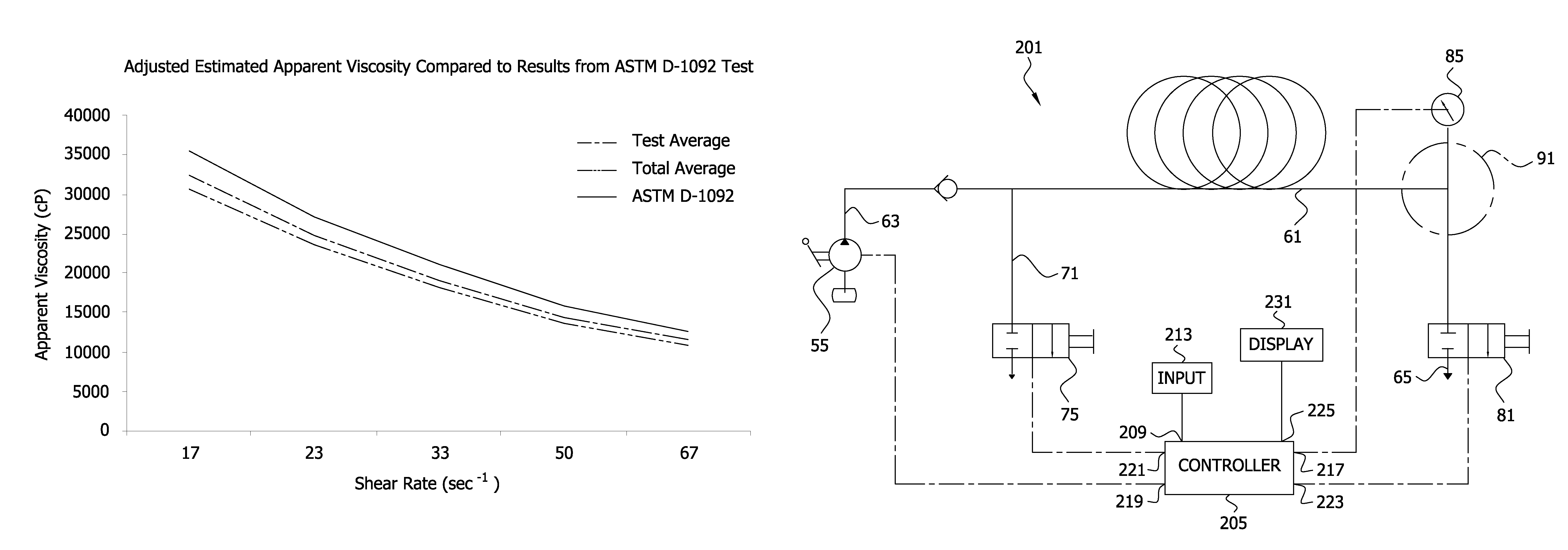
The following non-limiting example is provided to further illustrate steps (a) to (e) above. In this example, three tests were conducted, each involving steps (a) to (e). In each test, the “venting” interval was initiated when the pressure in the pressure zone, as measured by the pressure measuring device 85, reached about 1800 psi. During the venting interval, a pressure reading P was taken during the transition S2 (e.g., at about t=2 seconds). The tests results are tabulated below in Table 1.

TABLE 1Test123P (psi)496.9535.9514.5

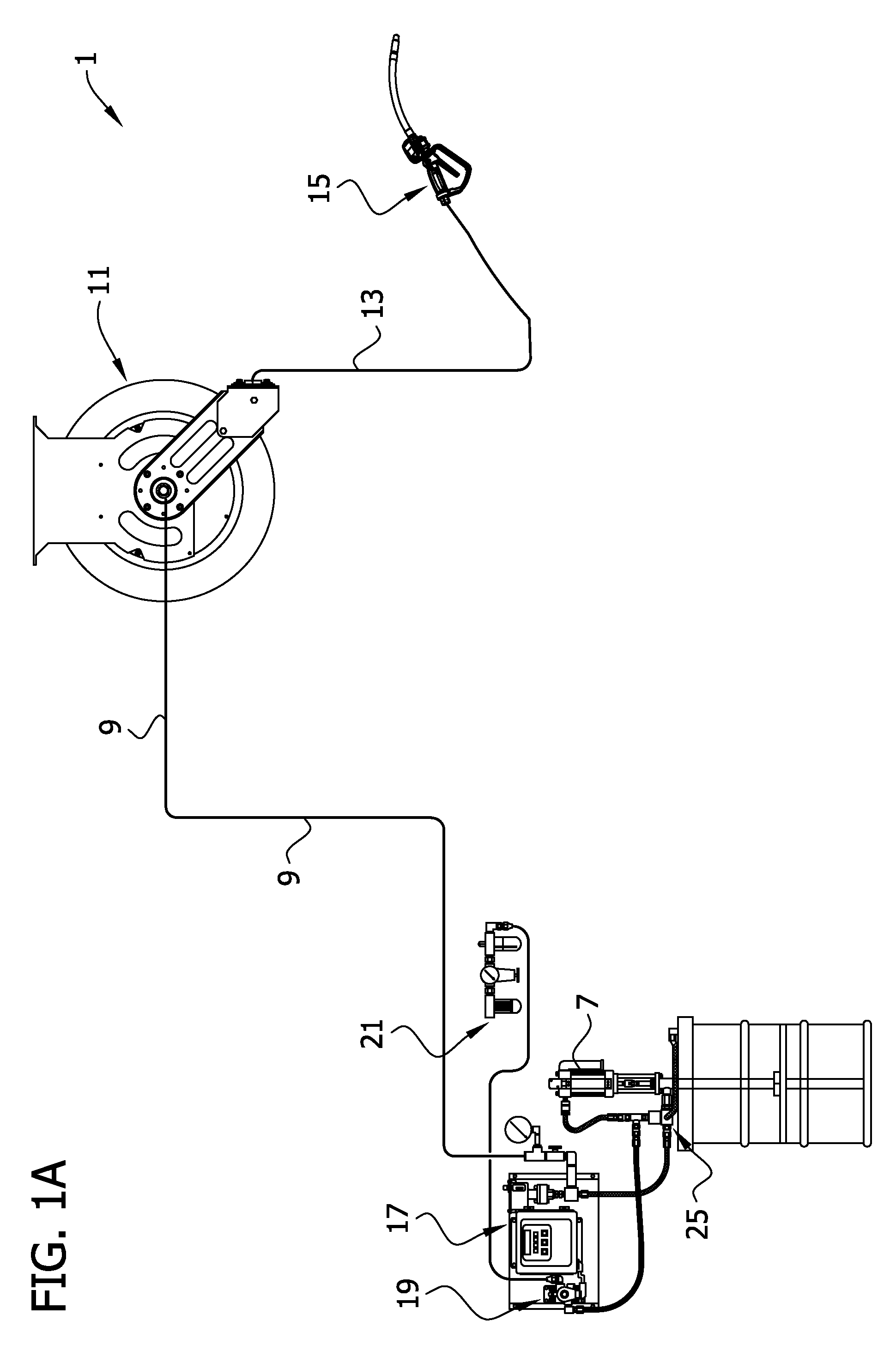
Using the information in Table 1, the shear stress was calculated using formula (1) τ=P*D / (4L), where D=0.19 in. (corresponding to the inside (flow) diameter of the coiled tube 19) and L=300 in. (corresponding to the length of the tube). This calculation resulted in the information in Table 2 below.

TABLE 2Test123P (psi)496.9535.9514.5τ = P * D / (4L)0.078680.084850.08146(lbs / in2)τ(mil-542451585026561664Pascal)

Using the information in Table 2, the estimated app...


PUM

PropertyMeasurementUnit
temperatureaaaaaaaaaa
timeaaaaaaaaaa

Abstract

Method and apparatus for estimating an apparent viscosity of a non-Newtonian fluid. The results may be used for selecting equipment for pumping systems.

Description

FIELD OF THE INVENTIONThe present invention generally relates to a system, apparatus and a method for estimating the apparent viscosity of a non-Newtonian fluid, such as lubrication greases, inks and adhesives. This information is useful in designing fluid flow systems, such as (but not limited to) fluid dispensing systems and lubrication systems.BACKGROUND OF THE INVENTIONApparent viscosity has been accepted increasingly by design engineers in sizing pumps and other components of fluid flow systems, such as grease lubrication systems. In general, the apparent viscosity of a fluid is defined as shear stress over shear rate. For non-Newtonian fluids, such as grease, the apparent viscosity changes at different shear rates. The standard method for measuring grease apparent viscosity is defined by ASTM D-1092. Using this method, the apparent viscosity of a non-Newtonian fluid can be measured at different shear rates. However, this method has several drawbacks. The test involves expensiv...

Claims


Application Information

Patent Timeline
Patent Type & Authority Patents(United States)
IPC IPC(8): G01N11/04G01N11/06
CPCG01N11/08G01N2011/0026
Inventor HE, CANLONGCONLEY, PAUL G.
Owner LINCOLN INDUSTRIES CORP
Why Eureka
Try Eureka