In-vehicle illuminating device

a technology for illuminating devices and vehicles, which is applied in the direction of fibre light guides, lighting and heating apparatus, instruments, etc., can solve the problems of inability to obtain a bright illuminating device, inability to efficiently guide the luminous flux, and large size of the illuminating device as a whole in the longitudinal direction, so as to achieve efficient guided, improve illumination efficiency, and efficiently guided

Inactive Publication Date: 2011-07-19
HONDA ACCESS CORP
View PDF13 Cites 3 Cited by
  • Summary
  • Abstract
  • Description
  • Claims
  • Application Information

AI Technical Summary

Benefits of technology

[0007]Therefore, in view of the problem described above, it is an object of the present invention to provide an in-vehicle illuminating device capable of efficiently guiding luminous flux emitted from a luminous source.
[0014]The in-vehicle illuminating device according to the first aspect of the present invention enables the luminous flux emitted from the luminous source to be efficiently guided into the rod-shaped light guiding body. Hence, the device can be improved in illumination efficiency.
[0015]The in-vehicle illuminating device according to the second aspect of the present invention enables the emitted luminous flux to be efficiently guided into the optical incidence plane of each rod-shaped light guiding body even if there are two or more rod-shaped light guiding bodies are provided. Hence, the device can be improved in illumination efficiency.

Problems solved by technology

In a case where such device is designed so that the luminous source is arranged coaxially with the rod-shaped light guiding body to emit luminous flux in parallel with a longitudinal direction of the rod-shaped light guiding body, however, there has been a problem that the in-vehicle illuminating device becomes too large in size as a whole in the longitudinal direction since the luminous source must be arranged adjacent to an end face of the end of the rod-shaped light guiding body in parallel therewith.
However, according to this prior art, there has also been a problem that due to the rod-shaped light guiding body being orthogonal to the luminous flux emitted from the luminous source, it is difficult to efficiently guide the luminous flux emitted from the luminous source into the light guide, thus making it impossible to obtain a bright illuminating device.

Method used


Image

  • In-vehicle illuminating device
  • In-vehicle illuminating device
  • In-vehicle illuminating device

Examples


Embodiment Construction

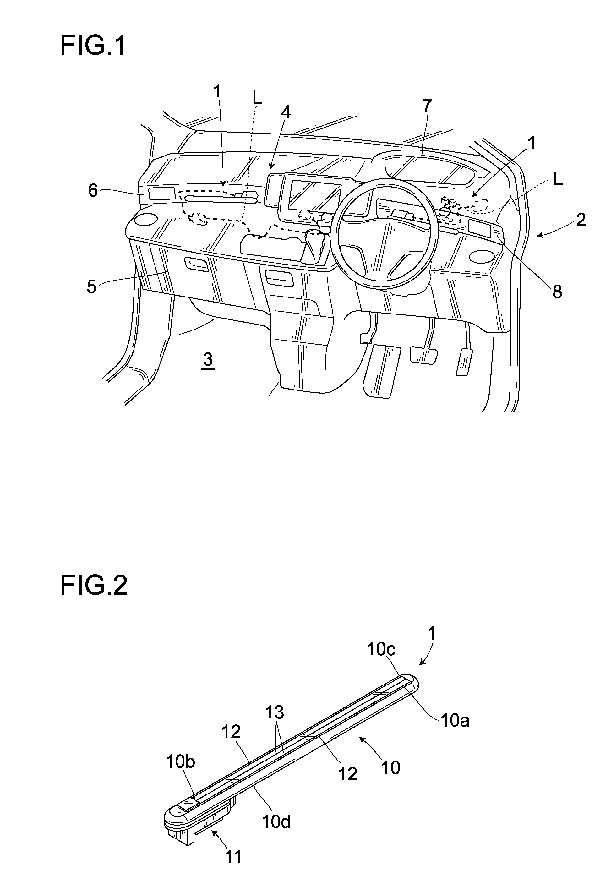
[0034]Hereunder is a description of a preferred embodiment of the present invention with reference to the accompanying drawings. An in-vehicle illuminating device 1 shown in FIG. 1 is mounted on an instrument panel 4 arranged in a vehicle interior 3 of a vehicle 2. According to the present embodiment, the device 1 is incorporated in a left outlet panel 6 provided at a top of a glove compartment 5 and in a right outlet panel 8 provided at a bottom of a meter panel 7 and is connected electrically with an electric power supply (not shown) through a wire harness L. Thus, the in-vehicle illuminating device 1 mounted on the instrument panel 4 is configured so as to illuminate the instrument panel 4 to thereby permit illumination to be provided to the vehicle interior 3 as an indirect illumination.

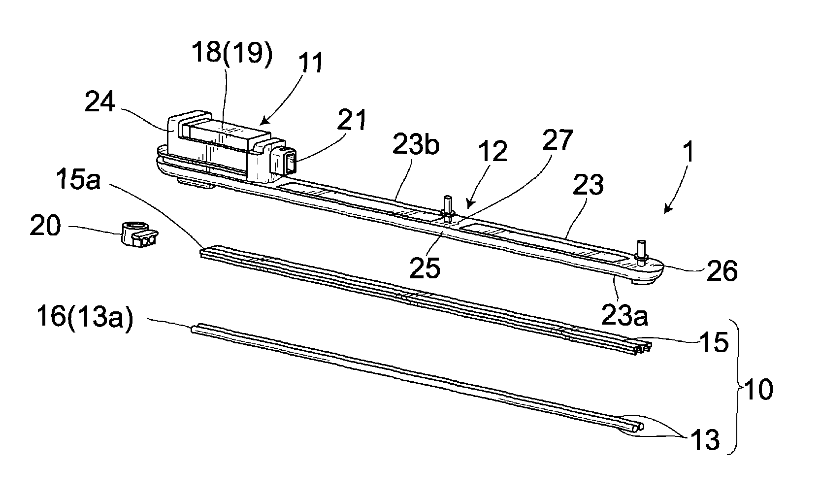
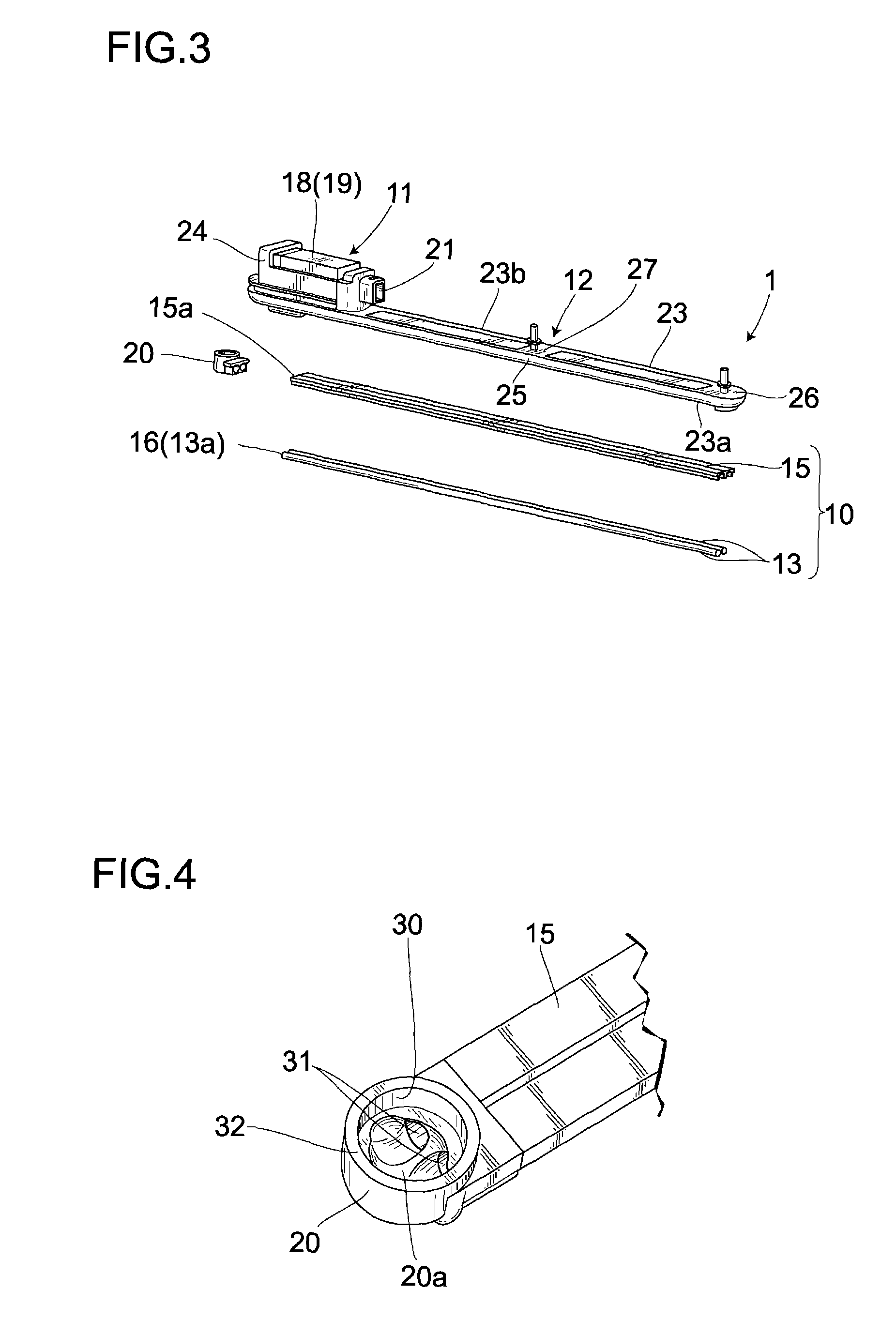
[0035]As shown in FIG. 2, the in-vehicle illuminating device 1 is provided with an optical guiding unit 10 and a luminous source unit 11, which are integrated with each other by means of a base 1...


PUM


Abstract

An in-vehicle illuminating device 1 capable of efficiently guiding luminous flux emitted from a luminous source to a light guiding body. The in-vehicle illuminating device 1 is provided with a rod-shaped light guiding body 13 which reflects, on its inner surface, light rays incident from an optical incidence plane 16 provided at an end 13a to guide the light rays to the other end longitudinally provided, a lamp 19 which emits light to a direction orthogonal to the longitudinal direction of the rod-shaped light guiding body 13 and is arranged in the vicinity of the optical incidence plane 16, and an light introducing body 20 for introducing the luminous flux emitted from the lamp 19 to the optical incidence plane 16. The light introducing body 20 allows the optical incidence plane 16 to be set within a range of the luminous flux emitted from the lamp 19.

Description

BACKGROUND OF THE INVENTION[0001]1. Field of the invention[0002]The present invention relates to an in-vehicle illuminating device, and more particularly, to an in-vehicle illuminating device suitably used for an in-vehicle illuminating system arranged in an in-vehicle instrument panel or the like.[0003]2. Description of the Related Art[0004]Heretofore, there has been known, as an in-vehicle illuminating device arranged in an in-vehicle instrument panel, for example, a device comprising a rod-shaped light guiding body and a luminous source, such as an LED (Light-Emitting Diode) arranged at an end of the rod-shaped light guiding body to guide luminous flux emitted from the luminous source from the first end of the rod-shaped light guiding body to the second end thereof.[0005]In a case where such device is designed so that the luminous source is arranged coaxially with the rod-shaped light guiding body to emit luminous flux in parallel with a longitudinal direction of the rod-shaped l...

Claims


Application Information

Patent Timeline
Patent Type & Authority Patents(United States)
IPC IPC(8): B60Q3/04F21W106/00
CPCB60Q3/14B60Q3/64B60Q3/78G02B6/0006G02B6/001B60Q3/10B60Q3/62F21S43/00
Inventor IWAI, SHIROKAWAMURA, TOMOKIMURABAYASHI, HIROTO
Owner HONDA ACCESS CORP
Why Eureka
Try Eureka