Electrical plug receiving connector

a technology for receiving connectors and plugs, applied in the direction of fixed connections, coupling device connections, contact members penetrating/cutting insulation/cable strands, etc., can solve the problem of limiting the number of plug-in connectors which can be installed, and achieve the effect of reducing crosstalk, reducing capacitive coupling between adjacent contact pairs, and reducing crosstalk

Active Publication Date: 2011-07-19
COMMSCOPE TECH LLC
View PDF44 Cites 6 Cited by
  • Summary
  • Abstract
  • Description
  • Claims
  • Application Information

AI Technical Summary

Benefits of technology

[0008]In a further preferred embodiment, wire connection contacts in a row which are associated with one another in pairs are aligned parallel to one another, whereas adjacent wire connection contacts of different contact pairs in a row are arranged with respect to one another such that they are rotated through 90° about the longitudinal axis of the wire connection contacts. As a result, the capacitive coupling between adjacent contact pairs is reduced which was increased by the reduction in the gap.

Problems solved by technology

Owing to the gap required between the two rows, the plug-in connector is relatively wide, which limits the number of plug-in c

Method used


Image

  • Electrical plug receiving connector
  • Electrical plug receiving connector
  • Electrical plug receiving connector

Examples


Embodiment Construction

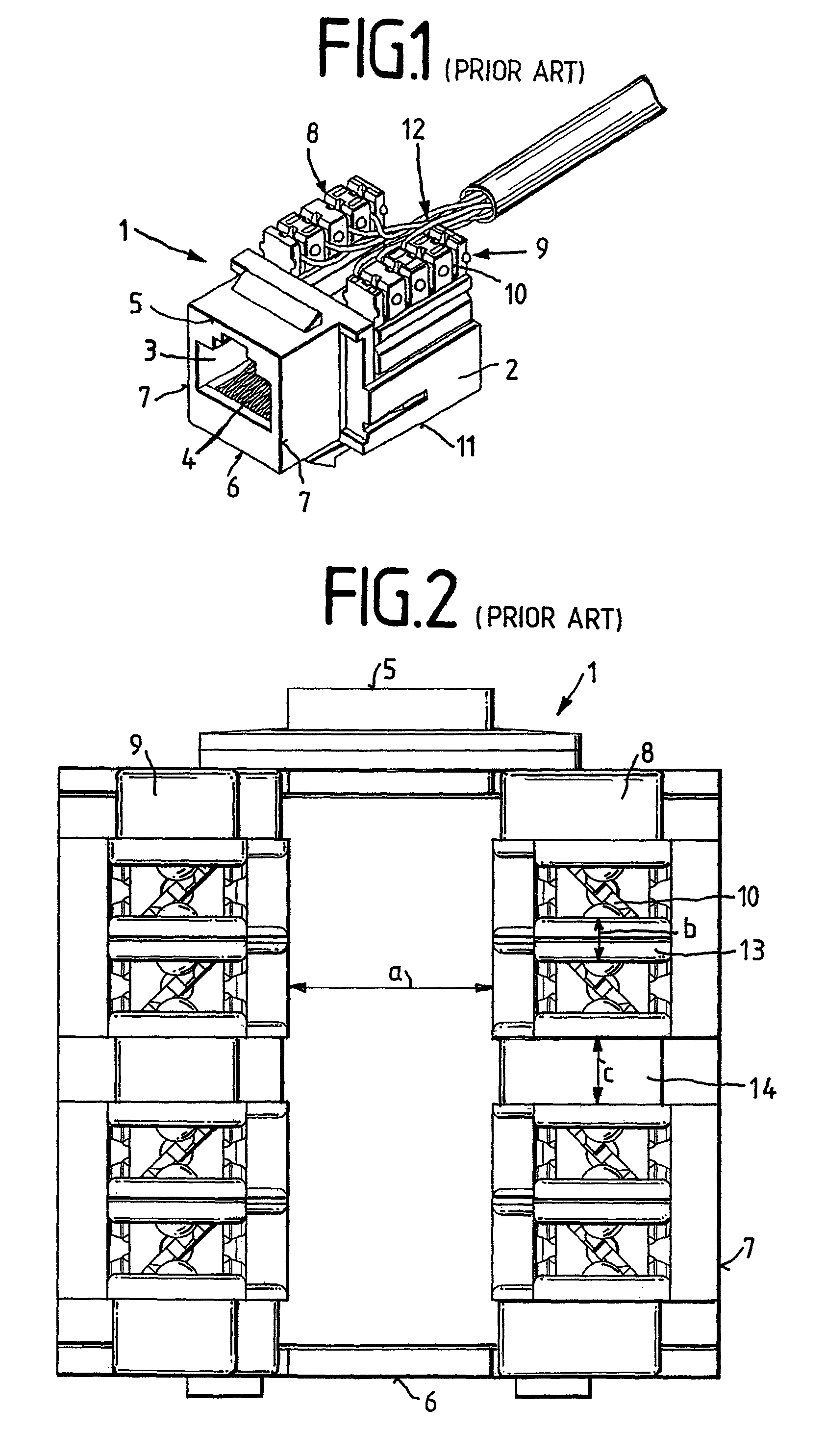
[0021]FIG. 1 illustrates an RJ45 socket in accordance with the prior art as an electrical plug-in connector 1. The plug-in connector 1 comprises a housing 2, which has a receiving opening 3, in which RF contacts 4 are arranged with which contact can be made by a mating plug. The housing has an upper edge 5, a lower edge 6 and two side edges 7. Two rows 8, 9 of wire connection contacts 10 which are in the form of insulation displacement contacts, are arranged on the upper side of the plug-in connector 1. In this case, the two rows extend parallel to a longitudinal edge 11 of the plug-in connector. In this case, the two rows 8, 9 have a predefined gap which makes it possible to push wires 12 into the wire connection contacts 10 using a connection tool.

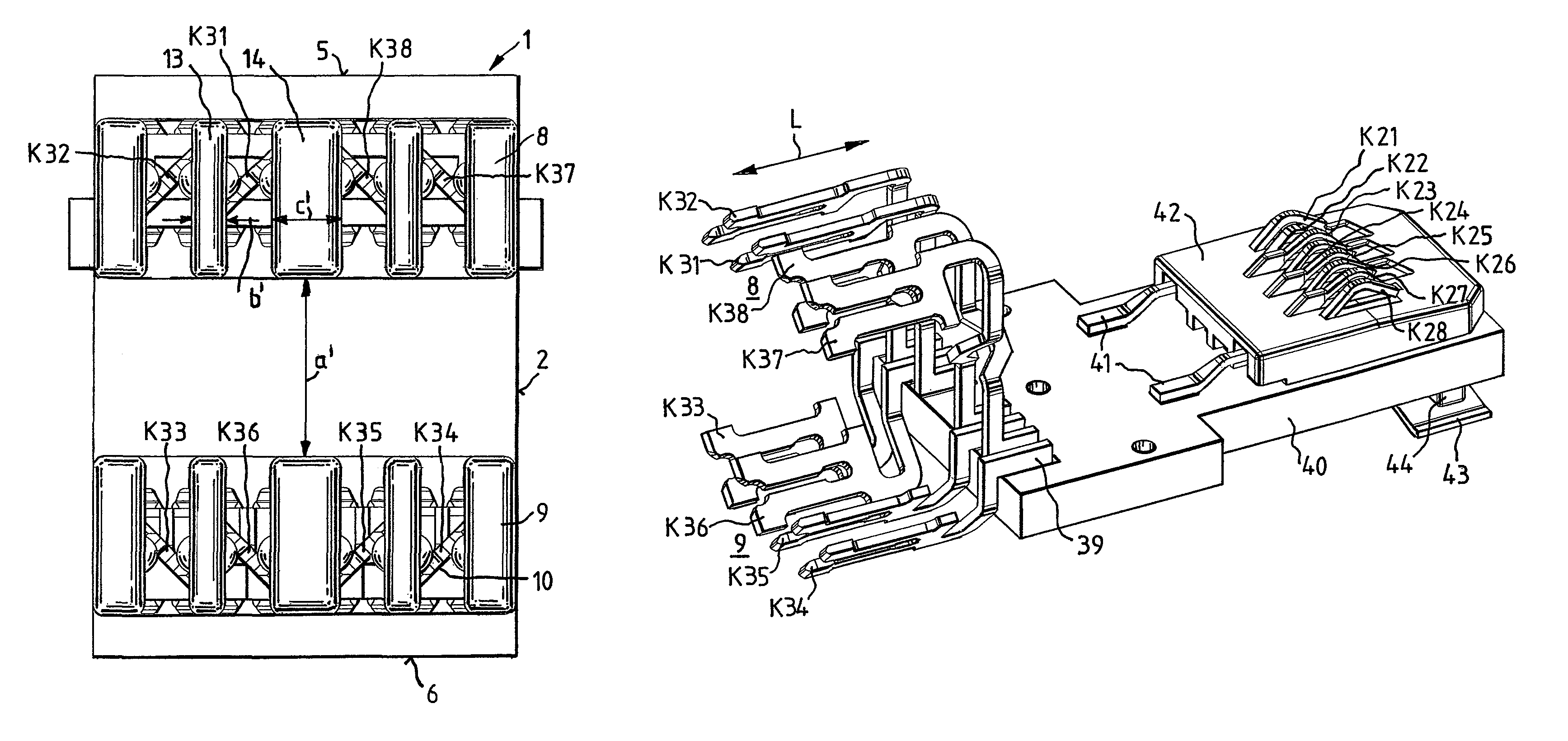
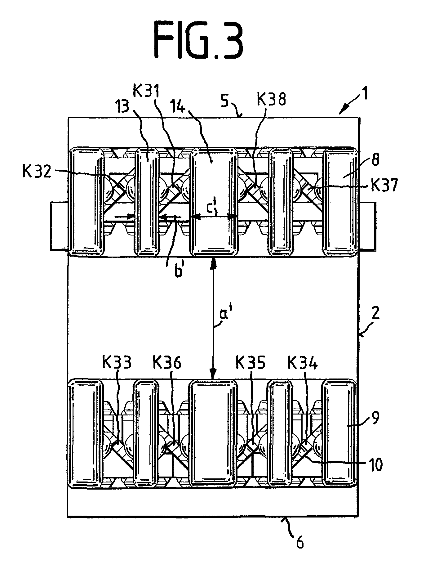
[0022]FIG. 2 illustrates an alternative design in accordance with the prior art. In this case, the two rows 8, 9 are not arranged on the upper side of the plug-in connector, but on the rear side. In this case, the two rows 8, 9 are arran...


PUM


Abstract

The invention relates to an electrical plug-in connector (1) for telecommunications and data systems technology, comprising electrically interconnected elastic high-frequency contacts (4) and core connection contacts (10). At least the high-frequency contacts (4) are arranged in a housing (2) comprising a receiving opening (3) for a counter plug-in connector, and the core connection contacts (10) are arranged in two parallel rows (8, 9). The distance between adjacent core connection contacts of a row is smaller than that between core connection contacts of different rows. The housing (2) has an upper edge (5), a lower edge (6) and two lateral edges (7), the two rows (8, 9) of core connection contacts (10) being parallel to the upper edge (5) of the housing (2).

Description

[0001]This application is a National Stage Application of PCT / EP2007 / 010933, filed 13 Dec. 2007, which claims benefit of Serial No. 10 2007 002 767.4, filed 18 Jan. 2007 in Germany and which applications are incorporated herein by reference. To the extent appropriate, a claim of priority is made to each of the above disclosed applications.BACKGROUND[0002]Such a generic electrical plug-in connector is previously known, for example, from EP 1 312 137 B1. Here, the wire connection contacts are formed by two rows of insulation displacement contacts, which are arranged parallel to the side edges of the plug-in connector on its rear side.[0003]DE 20 2005 001 178 U1 has further disclosed an RJ45 socket, in which the two rows of insulation displacement contacts are arranged on the upper side of the plug-in connector, the rows in each case being positioned at a right angle with respect to the upper edge, lower edge and the side edges.[0004]Owing to the gap required between the two rows, the ...

Claims


Application Information

Patent Timeline
IPC IPC(8): H01R4/24H01R4/26H01R24/58
CPCH01R13/6477H01R24/64H01R4/242H01R12/57H01R13/6315H01R13/6467H01R13/6658
Inventor HETZER, ULRICHMOSSNER, FRANK
Owner COMMSCOPE TECH LLC
Why Eureka
Try Eureka