
Electrical machine with grounded shield arrangement

a shield arrangement and shield technology, applied in the field of electric machines, can solve the problems of not being able to use known principles for all machine types, affecting the protection effect of shielding, and damage to bearings and lubricants provided in bearings,

Pending Publication Date: 2022-08-11
EBM PAPST MULFINGEN GMBH & CO KG
View PDF4 Cites 0 Cited by
  • Summary
  • Abstract
  • Description
  • Claims
  • Application Information

AI Technical Summary

Benefits of technology

The patent text describes a way to create a shielded space where the stator winding and its support are located. This shielding helps reduce the impact of unwanted electrical coupling between parts. It also prevents the formation of harmful electrical currents and voltages that can damage the bearings and cause voltage flashover. The two shielding units should be placed in a space that is completely surrounded by the central body, bearings, and rotor. The technical effects of this approach include improved efficiency, reduced risk of damage, and improved performance of the motor.

Problems solved by technology

Due to this common mode voltage, parasitic capacitances may become effective in the electrical machine that can then be responsible for increased wear or damages.
For example, breakthroughs or light arcs can occur in the region of the bearing arrangement due to a parasitic capacitance and depending on the amount of the common mode voltage, whereby the bearing as well as also the lubricant provided in the bearing can be damaged or subject to increased wear.
It has, however, shown that the known principles are partly not usable for all machine types and depending on the machine type no sufficient protection effect is entailed for the bearing arrangement.

Method used


Image

  • Electrical machine with grounded shield arrangement
  • Electrical machine with grounded shield arrangement
  • Electrical machine with grounded shield arrangement

Examples


Embodiment Construction

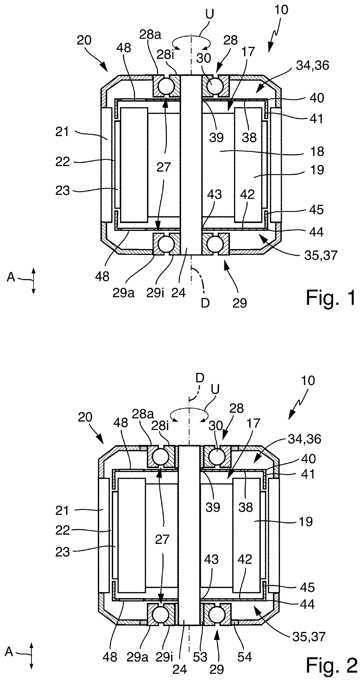
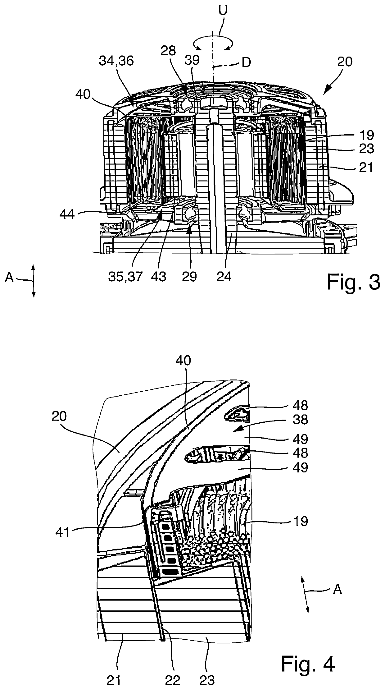
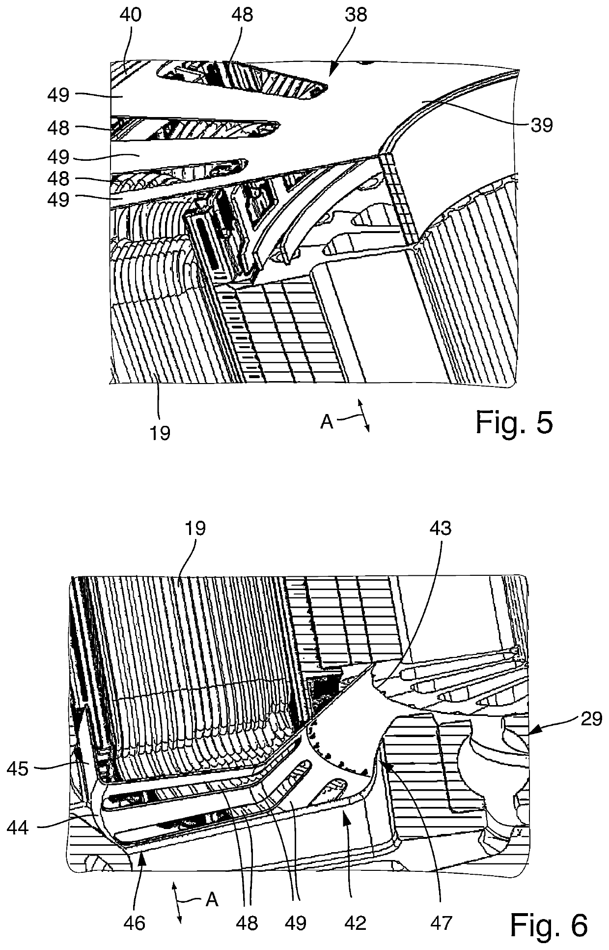
[0052]In FIGS. 1 and 2 an embodiment of an electrical machine 10 is illustrated respectively that can be operated as motor and thus can form an electric motor. The electrical machine 10 can be, for example, an electrical machine that can be operated by means of alternating voltage, preferably multi-phase and according to the example, three-phase alternating voltage. The operation of an electrical machine 10 by means of three-phase alternating voltage is schematically illustrated in FIG. 9. The electrical machine is connected via a converter circuit 11 to phase voltages U1, U2, U3 of a three-phase alternating voltage power grid. In the embodiment the converter circuit 11 has rectifier 12 that rectifies the three-phase alternating voltage and provides a direct voltage in a DC link 13 that is converted into a multi-phase and according to the example three-phase alternating voltage by means of an inverter 14 of converter circuit 11 for producing a rotating field in the electrical machin...


PUM


Abstract

An electrical machine including a stator, a rotor and a bearing arrangement having a first bearing and a second bearing on opposite sides of the stator as well as a shielding arrangement comprising a first shielding unit and a second shielding unit. The rotor is rotatably supported around a rotation axis by means of bearings. The shielding units are electrically conductive and comprise a ring part in each case that extends originating from a radial inner end to a radial outer end away from the rotation axis. Preferably each shielding unit has a circumferential part on its radial outer end that extends in a continuous ring-shaped manner around rotation axis and is arranged in overlapping manner with the adjacent axial end of stator winding in axial direction. The circumferential parts are preferably completely closed, whereas the ring parts can comprise through holes.

Description

CROSS REFERENCE TO RELATED APPLICATIONS[0001]This application claims priority under 35 U.S.C. § 119 to the following German Patent Application No. 10 2021 103 277.6, filed on Feb. 11, 2021, the entire contents of which are incorporated herein by reference thereto.TECHNICAL FIELD[0002]The invention refers to an electrical machine comprising a stator, a rotor rotatable around a rotation axis and a bearing assembly for supporting the rotor.BACKGROUND[0003]The electrical machine is particularly an electrical machine that can be operated with alternating current and preferably with 3-phase alternating current, e.g. a synchronous machine or asynchronous machine.[0004]In the motor operation the electrical machine operates with an electromagnetic rotating field that is created by means of a stator winding and serves to move the rotor. For example, the rotor can have permanent magnets. The electrical machine is not directly operated by one or more phases of the power grid, but a converter is...

Claims


Application Information

Patent Timeline
IPC IPC(8): H02K5/173H02K11/01H02K11/40
CPCH02K5/1732H02K11/40H02K11/0141H02K11/014
Inventor BUERKERT, MARTINMUELLER, RAINERHAEFNER, JOCHENSCHROTH, SEBASTIAN
Owner EBM PAPST MULFINGEN GMBH & CO KG
Learn More