Semiconductor package with air gap and manufacturing method thereof

a technology of semiconductor packaging and air gap, which is applied in the field of semiconductor packaging, can solve the problems of physical limitations of the scaling of semiconductor packaging that can be achieved, and still challenges to be handled for the 3d packaging technology, so as to improve the signal transmission between the semiconductor structure, reduce the rc delay of the conductive component, and reduce the coupling between the conductive components.

Active Publication Date: 2021-11-04
NAN YA TECH
View PDF3 Cites 1 Cited by
  • Summary
  • Abstract
  • Description
  • Claims
  • Application Information

AI Technical Summary

Benefits of technology

[0024]In conclusion, the semiconductor package according to embodiments of the present disclosure includes two semiconductor structures bonded with each other, and includes air gaps sealed at an interface between the semiconductor structures. Some of the air gaps are located between conductive components configured to establish electrical connection between the semiconductor structures. Because of a low dielectric constant of air, a capacitive coupling between these conductive components can be reduced by disposing the air gaps in between. Consequently, RC delay of the conductive components can be lowered. Therefore, signal transmission between the semiconductor structures can be improved.

Problems solved by technology

However, there are physical limitations to the scaling of semiconductor packages that can be achieved in two dimensions (2D).
Nevertheless, there are still challenges to be handled for the 3D packaging technology.

Method used


Image

  • Semiconductor package with air gap and manufacturing method thereof
  • Semiconductor package with air gap and manufacturing method thereof
  • Semiconductor package with air gap and manufacturing method thereof

Examples


Embodiment Construction

[0031]The following disclosure provides many different embodiments, or examples, for implementing different features of the provided subject matter. Specific examples of components and arrangements are described below to simplify the present disclosure. These are, of course, merely examples and are not intended to be limiting. For example, the formation of a first feature over or on a second feature in the description that follows may include embodiments in which the first and second features are formed in direct contact, and may also include embodiments in which additional features may be formed between the first and second features, such that the first and second features may not be in direct contact. In addition, the present disclosure may repeat reference numerals and / or letters in the various examples.

[0032]This repetition is for the purpose of simplicity and clarity and does not in itself dictate a relationship between the various embodiments and / or configurations discussed.

[0...


PUM

PropertyMeasurementUnit
temperaturesaaaaaaaaaa
conductiveaaaaaaaaaa

Abstract

The present application provides a semiconductor package with air gaps for reducing capacitive coupling between conductive features and a method for manufacturing the semiconductor package. The semiconductor package includes a first semiconductor structure and a second semiconductor structure bonded with the first semiconductor structure. The first semiconductor structure has a first bonding surface. The second semiconductor structure has a second bonding surface partially in contact with the first bonding surface. A portion of the first bonding surface is separated from a portion of the second bonding surface, a space between the portions to of the first and second bonding surfaces is sealed and forms an air gap in the semiconductor package.

Description

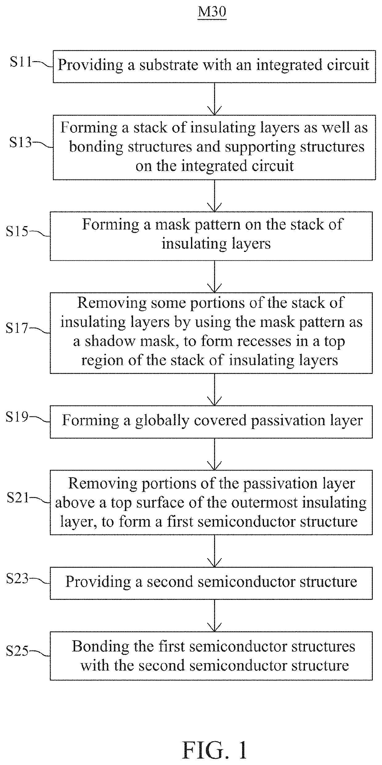
TECHNICAL FIELD[0001]The present disclosure relates to a semiconductor package and a manufacturing method thereof, and more particularly, to a semiconductor package with air gaps for reducing capacitive coupling between conductive features and a method for manufacturing the semiconductor package.DISCUSSION OF THE BACKGROUND[0002]In recent years, the semiconductor industry has experienced rapid growth due to continuous improvement in integration density of various electronic components. These continuously scaled electronic components require smaller packages that occupy less area than previous packages. However, there are physical limitations to the scaling of semiconductor packages that can be achieved in two dimensions (2D). While 2D scaling remains an option for new designs, adopting three-dimensional (3D) packaging schemes that utilize the z-direction has become a focus of research in the industry. Nevertheless, there are still challenges to be handled for the 3D packaging techno...

Claims


Application Information

Patent Timeline
Patent Type & Authority Applications(United States)
IPC IPC(8): H01L23/532H01L23/00H01L25/065H01L21/768H01L25/00
CPCH01L23/53295H01L24/03H01L24/05H01L25/0657H01L24/80H01L2924/30105H01L21/76877H01L25/50H01L2224/05557H01L2224/80009H01L21/76802H01L23/5386H01L23/49811H01L23/49816H01L23/49838H01L21/76895H01L21/7682H01L24/81H01L2224/81986H01L23/5222H01L23/552H01L25/16H01L2225/06524H01L2224/08145H01L24/17H01L24/16H01L24/11H01L24/13H01L2224/80895H01L2224/80896H01L24/08H01L2224/0401H01L2224/0603H01L2224/06051H01L2224/80006H01L2224/8003H01L2224/80097H01L2224/80906H01L2224/80948H01L2224/80357H01L2224/80365H01L2224/0345H01L2224/0346H01L2224/03616H01L2224/05647H01L2224/05181H01L2224/05166H01L2224/05186H01L2224/05686H01L2224/05666H01L2224/80379H01L2224/05681H01L2224/13147H01L2924/00014H01L2924/04953H01L2924/04941H01L2924/013H01L2924/00013H01L2924/05042H01L2924/05442H01L2924/059
Inventor HUANG, TSE-YAO
Owner NAN YA TECH
Why Eureka
Try Eureka