Conveyor belt junction element

a technology of junction elements and conveyor belts, applied in the direction of belt fastenings, v-belt fastenings, ropes and cables for vehicles/pulleys, etc., can solve the problems of a great deal of care to be taken in regards to the preparation of ends, a great deal of rigour, and a large time-consuming and labor-intensive tim

Active Publication Date: 2011-07-19
ASER
View PDF12 Cites 11 Cited by
  • Summary
  • Abstract
  • Description
  • Claims
  • Application Information

AI Technical Summary

Benefits of technology

[0021]According to an advantageous improvement of the invention which provides increased strength to the half-junctions, the junction is characterised in that the bush inserts are made in the female half-junctions so that the bush drives the edges of the hole of the two sections of the core that surround the bush perpendicularly in the general plane of these layers and are therefore solidly attached to the female half-junction in two perpendicular planes by the constituent material and the sections of the core that surround them.

Problems solved by technology

Vulcanisation provides excellent results, but it has the disadvantage of the time required to perform it, taking up to 24 hours, which is a definite handicap.
As with vulcanisation, it requires a great deal of care to be taken as regards the preparation of the ends, and great rigour as regards the conditions under which the technical glues are applied.
However, this device has problems caused by the wear of the clips and of the linking rods as well as by localised wrenching, which require repairs and increased stopping times of the conveyor belts.
However, these junctions, which have solved many problems in certain industries, in particular in heavy extraction industries, for transporting coal, minerals, phosphates and other heavy loose products, still encounter, in certain cases, problems with wrenching of the flanges which, although they are bevelled in the direction of the thickness at the end that is in contact with the conveyor belt, have a thickness that sometimes catches with the scrapers with which these belts are equipped.
However, the junction devices provided in these patents of the prior art were difficult to implement and the handling of the ends of the conveyor belt in order to present them for mutual attachment was very complex.
Moreover, the attachment means, slats or rods passing through the transverse holes alternately belonging to either one of the ends of the conveyor belt were very difficult to install, in particular in the heavy conveyor belts.
Finally, the resistance to traction of these junctions with transverse slats was not satisfactory.
Indeed, the transverse slats or rods caused shearing effects in the constituent material, present between the two layers of core placed respectively above and under the transverse holes, which resulted in wear and tear of the junctions.

Method used


Image

  • Conveyor belt junction element
  • Conveyor belt junction element
  • Conveyor belt junction element

Examples


Embodiment Construction

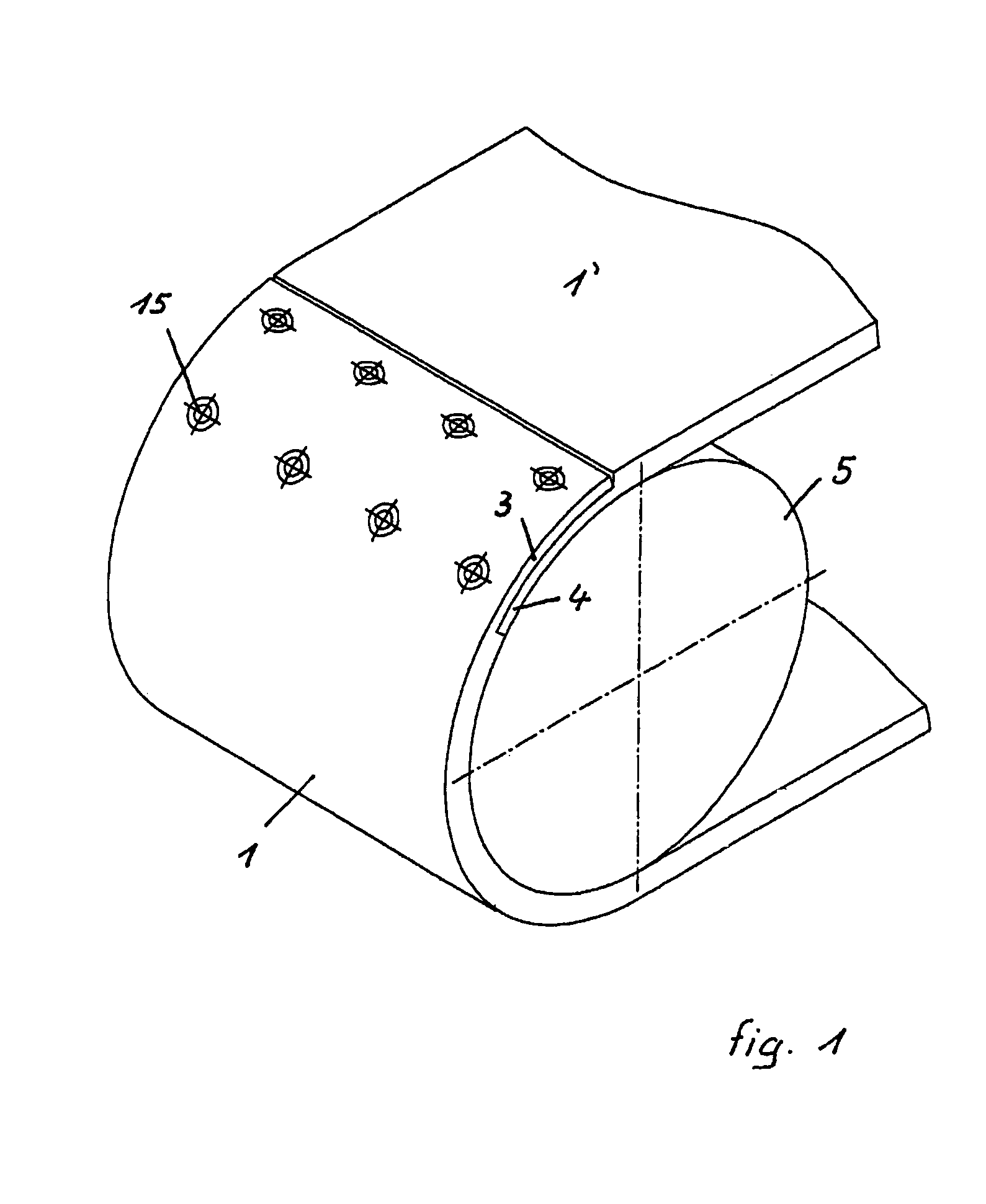
[0044]In FIG. 1, a roller 5 is used for driving the ends 1, 1′ of the conveyor belt, notably comprising a male half-junction 3 and a female half-junction 4 assembled by means of screws 15. This junction only shows the general principle of the junctions according to the invention since, as already mentioned above, it has a front section of the male half-junction 3 which extends across the entire width and which can therefore catch easily with the scrapers.

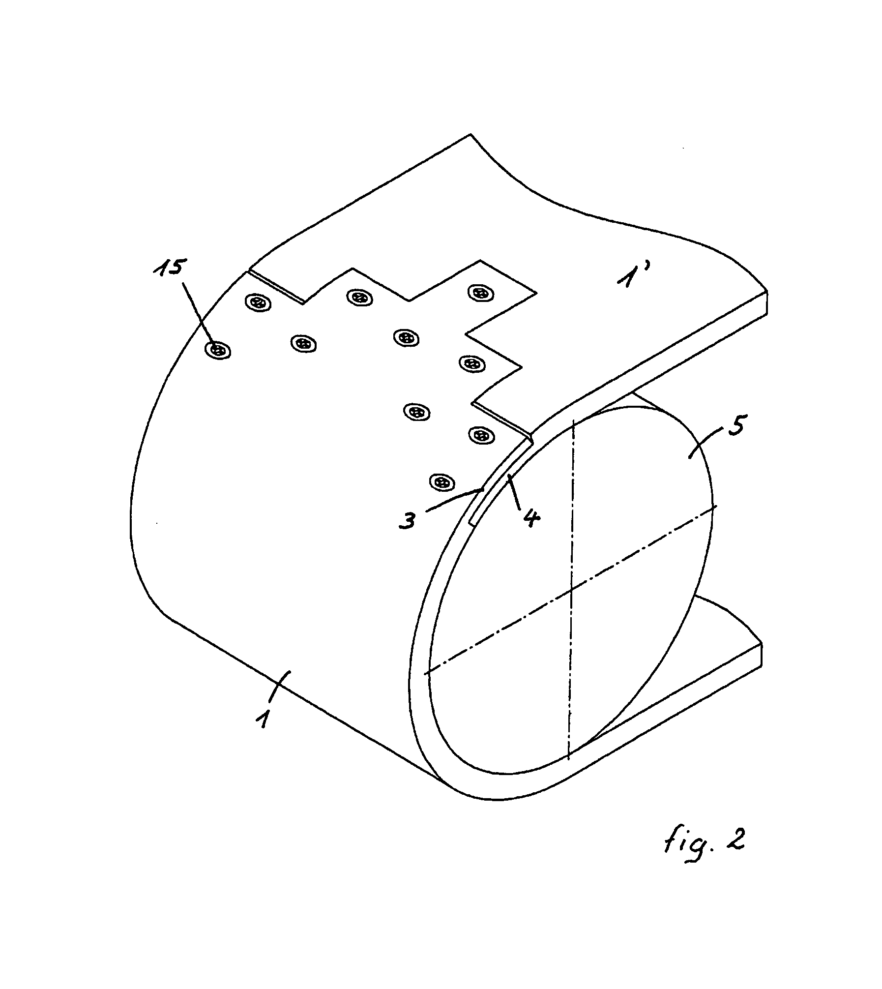
[0045]FIG. 2 shows another more elaborate junction according to the invention, in the same position as the junction in FIG. 1. It is remarkable that the front edge of the male half-junction 3 has sections that are shifted in the longitudinal direction, which make it possible to prevent any possible catching of the scrapers over too considerable a section of the width at the same time.

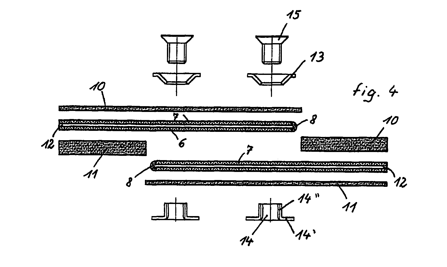
[0046]FIG. 3 shows a perspective view of the folded sections of the core 7, which are folded over the cores 6 level with the longitudinally shifted fol...


PUM


Abstract

A junction for a conveyor belt that includes first and second half-junctions attachable to one end of the conveyor belt. Each of the half-junctions having substantially matching shapes that allow the half-junctions to be interlinked. The half-junctions include a flexible core, and being respectively equipped with cup inserts and bush inserts allowing the passage of an assembly mechanism. Each of the cores extend towards the inside of each half-junction forming a fold at a free edge of each of the half-junctions. The top level of the first half-junction contains the fold and in which a front edge of the bottom level has substantially the same shape as a front edge of the top level, but is shifted towards the rear at least by the distance that separates the front edge of the top level from the cup inserts that are the furthest from the front edge of the top level. The second half-junction has a top level in which the shape of a front edge of the top level matches that of the front edge of the matching first half-junction, and a bottom level containing the fold and the bush inserts. The front edge of the bottom level is shifted towards the front in relation to the front edge of the top level, and its shape matches that of the front edge of the bottom level of the first half-junction. The attachment of the first and second half-junctions with each other is provided by fasteners.

Description

FIELD OF THE INVENTION[0001]The present invention relates to a junction element built into the ends of a conveyor belt.BACKGROUND OF THE INVENTION[0002]Conveyor belts have been known for a long time, generally made from rubber or a synthetic material and comprising a flexible inner core.[0003]Various methods have been used in the past to provide the junction between the ends of a conveyor belt that is initially open at both ends, with a view to transforming it into a so-called endless operational conveyor belt. These junction methods are also used for the insertion of new sections in a current conveyor belt, with a view to extending the length of said current belt, for example to follow-up the progress of mining work or to replace a part of the conveyor belt that has been damaged.[0004]Notable among these methods is the vulcanisation of the ends, with a prior operation of baring the core and forming degrees with shapes that complement the two ends of the conveyor belt. Vulcanisation...

Claims


Application Information

Patent Timeline
Patent Type & Authority Patents(United States)
IPC IPC(8): F16G3/00F16G3/08
CPCF16G3/08
Inventor JAKOB, HORST
Owner ASER
Why Eureka
Try Eureka