Packing buffer member

a buffer member and buffer technology, applied in the field of packaging buffer members, can solve the problems of large space needed for buffer members, increased storage costs, and increased storage costs, and achieve the effect of reducing the amount of plastic sheet material

Inactive Publication Date: 2011-07-19
CANON KK
View PDF3 Cites 0 Cited by
  • Summary
  • Abstract
  • Description
  • Claims
  • Application Information

AI Technical Summary

Benefits of technology

[0007]The present invention provides a packing buffer member in which the used amount of plastic sheet material is reduced.

Problems solved by technology

Therefore, if buffer members as described above are used, there were problems in the store workability.
For example, the buffer members needed much space when they are stored.
Such a configuration may need more depth to be molded in accordance with the shape of the object to be packed, and it is also technically difficult to mold such a configuration.

Method used


Image

  • Packing buffer member
  • Packing buffer member
  • Packing buffer member

Examples


Embodiment Construction

[0017]Exemplary embodiments of the present invention will be described below in detail with reference to the accompanied drawings.

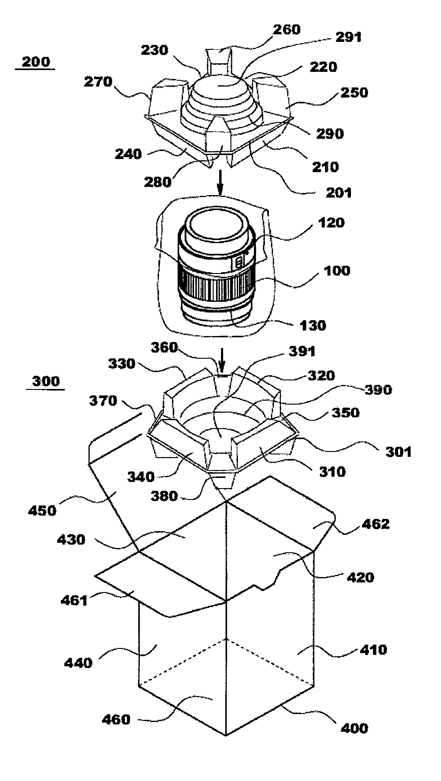
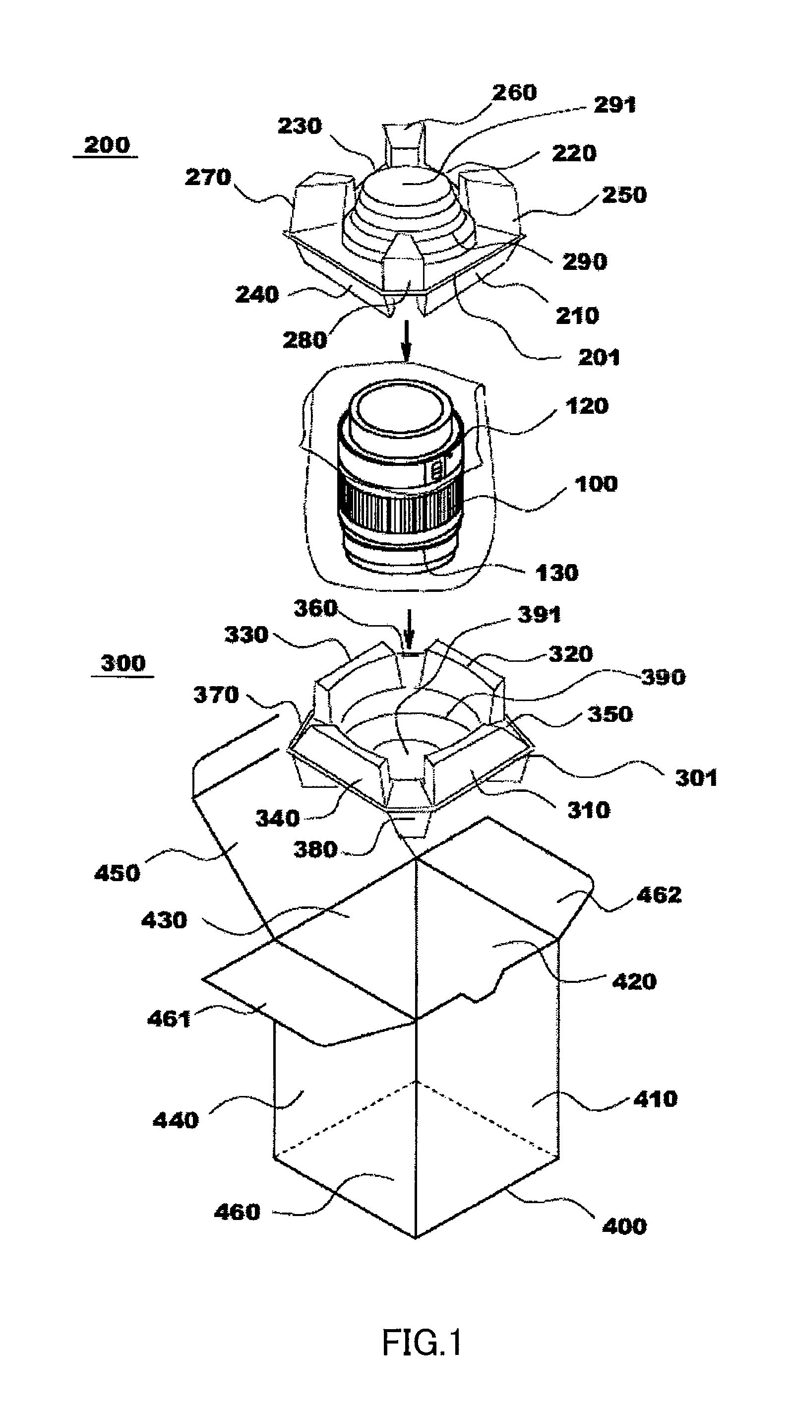
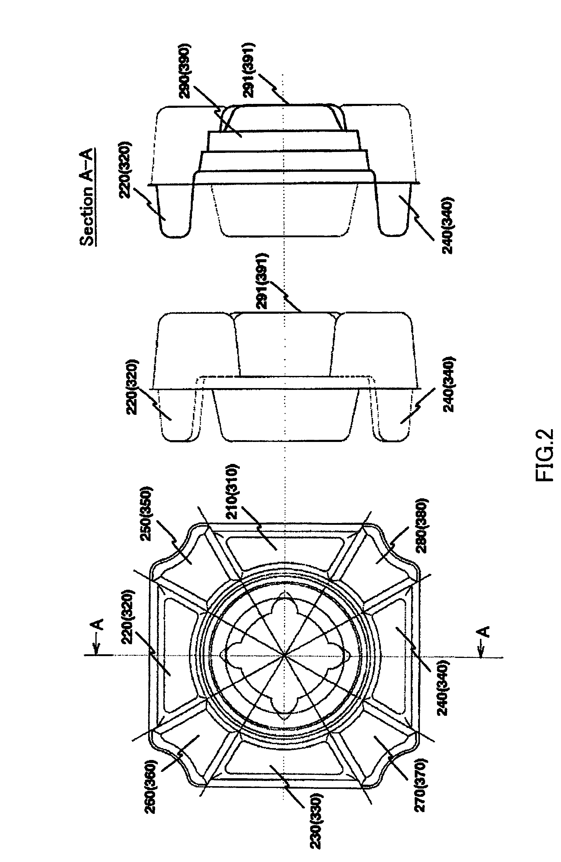
[0018]FIG. 1 is a perspective view that shows a whole configuration including a pack 400, where a packing buffer member of the present embodiment is applied. FIG. 2 is an outline plan view of the packing buffer member and a cross-sectional view showing it from the direction of Section A-A. FIG. 3 is a perspective view of the packing buffer member. FIG. 4A is a plan view of the packing buffer member. FIG. 4B is a cross-sectional view of Section B-B in FIG. 4A. FIG. 4C is a cross-sectional view of a conventional configuration. Hereinafter, the present invention will be described with reference to FIGS. 1 to 4.

[0019]As shown in FIGS. 1 to 4, in the present embodiment, an object to be packed 100 such as a precision apparatus is packed using two packing buffer members of an upper packing buffer member 200 and a lower packing buffer member 300.

[0020]In FIG. 1, ...


PUM

PropertyMeasurementUnit
areaaaaaaaaaaa
shapeaaaaaaaaaa
heightaaaaaaaaaa

Abstract

A packing buffer member of the present invention is a packing buffer member 200 or 300 that is to be placed inside a pack 400 with an object to be packed 100, and includes first hollow convex parts 210, 220, 230 and 240 (third hollow convex parts 310, 320, 330 and 340) that are formed in a first direction relative to a forming base surface 201 or 301 and that contact with the object to be packed 100 to hold the object to be packed 100 and second hollow convex parts 250, 260, 270 and 280 (the fourth hollow convex parts 350, 360, 370 and 380) that are formed in a second direction opposite to the first direction relative to the forming base surface 201 or 301 and that contact inside the pack. The packing buffer member 200 or 300 is formed by a plastic sheet.

Description

BACKGROUND OF THE INVENTION[0001]The present invention relates to a packing buffer member, and more particularly to a packing buffer member for packing a precision apparatus such as a lens that is subject to breakage.[0002]Conventionally, there was a packing method as shown in FIG. 5. This method is a method for packing an object to be packed 10 such as precision apparatuses using an upper packing buffer member 20 and a lower packing buffer member 30. The upper packing buffer member 20 and the lower packing buffer member 30 are buffer members that have a configuration in which a buffer part that absorbs a shock for the object to be packed 10 from outside the pack and a holding part that holds the object to be packed 10 are integrated.[0003]The upper packing buffer member 20 and the lower packing buffer member 30 have a good performance in buffering the object to be packed 10. However, as shown in a side view of lower right of FIG. 5, height A of the upper packing buffer member 20 an...

Claims


Application Information

Patent Timeline
Patent Type & Authority Patents(United States)
IPC IPC(8): B29D22/00B32B1/08B29D23/00
CPCB65D5/5069B65D81/025B65D81/05Y10T428/13Y10T428/239Y10T428/1352Y10T428/1397
Inventor TANAKA, MUTSUMIHISADOME, YOSHIHIKOKOJIMA, YUKINOBUNARASAWA, TAKASHI
Owner CANON KK
Why Eureka
Try Eureka