Brush, in Particular Toothbrush, and Method of Manufacturing the Same

a technology of toothbrushes and molded surfaces, applied in the field of toothbrushes, can solve the problems of not being able to achieve complete tightness, unable to meet the visual and design requirements of hygiene products, and the surface of intermediate products molded in this way, so as to achieve the effect of reducing plastic weigh

Pending Publication Date: 2022-05-19
M C SCHIFFER
View PDF0 Cites 0 Cited by
  • Summary
  • Abstract
  • Description
  • Claims
  • Application Information

AI Technical Summary

Benefits of technology

[0011]The brush according to the present invention has a handle stem formed from a foamed plastic. The foamed plastic may also form the brush neck. The foamed plastic allows a brush body to be produced in the usual and previously known dimensions, but using a reduced amount of plastic. The foaming results in improved use of the amount of plastic material introduced during injection molding to form the brush body. In total, the brush is lighter. It may be manufactured at a lower cost because a reduced weight of plastic has to be used to form the brush body without sacrificing the dimensional design of the brush.
[0014]The foamed plastic may also form parts of the brush head. In the case of multiple bristle carriers provided in the area of the brush head, the foamed plastic may connect them with each other or surround them. As a result, the brush head, too, is formed into an aesthetically pleasing segment of the brush body by the outer enclosure with the foamed plastic, albeit with reduced plastic weight.

Problems solved by technology

Complete tightness is, however, not achieved at this point.
Thus, upon overmolding the thickening and the attachment-side end of the bristle bundle a reduced injection pressure has to be applied, which, however, results in a surface of the intermediate product molded in this way that does not always meet the visual and design requirements to be placed on a hygiene product such as a toothbrush.

Method used


Image

  • Brush, in Particular Toothbrush, and Method of Manufacturing the Same
  • Brush, in Particular Toothbrush, and Method of Manufacturing the Same
  • Brush, in Particular Toothbrush, and Method of Manufacturing the Same

Examples


second embodiment

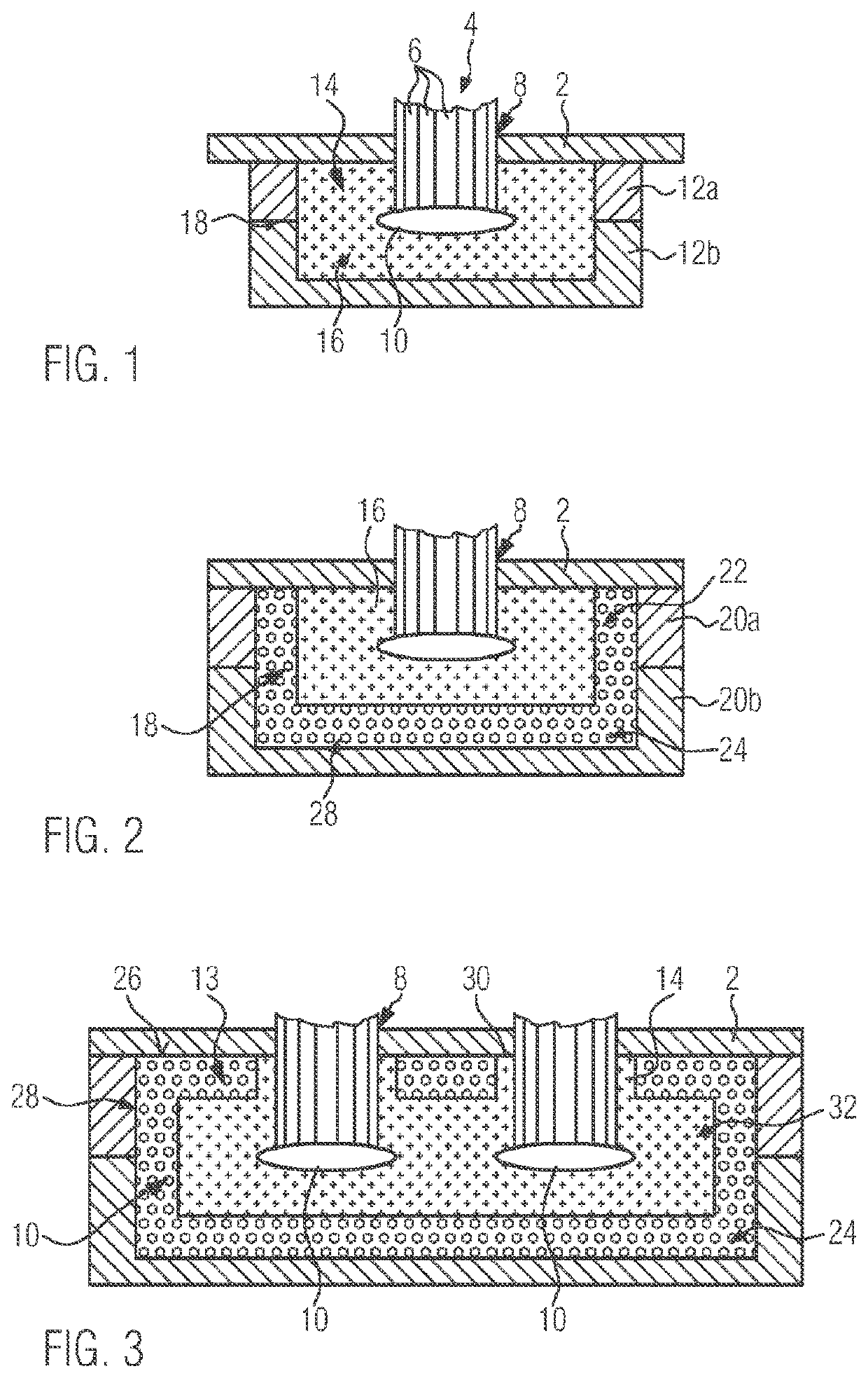
[0042]FIG. 3 shows an example of an embodiment modified with respect to FIGS. 1 and 2 after injection of the foamed plastic 24. Identical components are marked with the same reference signs. The second embodiment according to FIG. 3 differs above all in that an upper outer surface of the brush head 28 shown in cross-section, which is penetrated by the bristle bundles 4 and is marked with reference sign 26, is formed quite predominantly by the foamed plastic 24. Only an exemplary circular ring surface 30 circumferentially surrounds the bristle bundle 4, which in this case has a circular cross-section.

[0043]Accordingly, the surface regions of the brush head 28 penetrated by the bristle bundles 4 are formed by the hard component 16, but the upper outer surface 26 is otherwise predominantly formed by the foamed plastic 24. The variant shown also leads to a completely form-fitting sealing of the bristle carrier formed by the hard component 16 and identified by reference sign 32.

[0044]FIG...

first embodiment

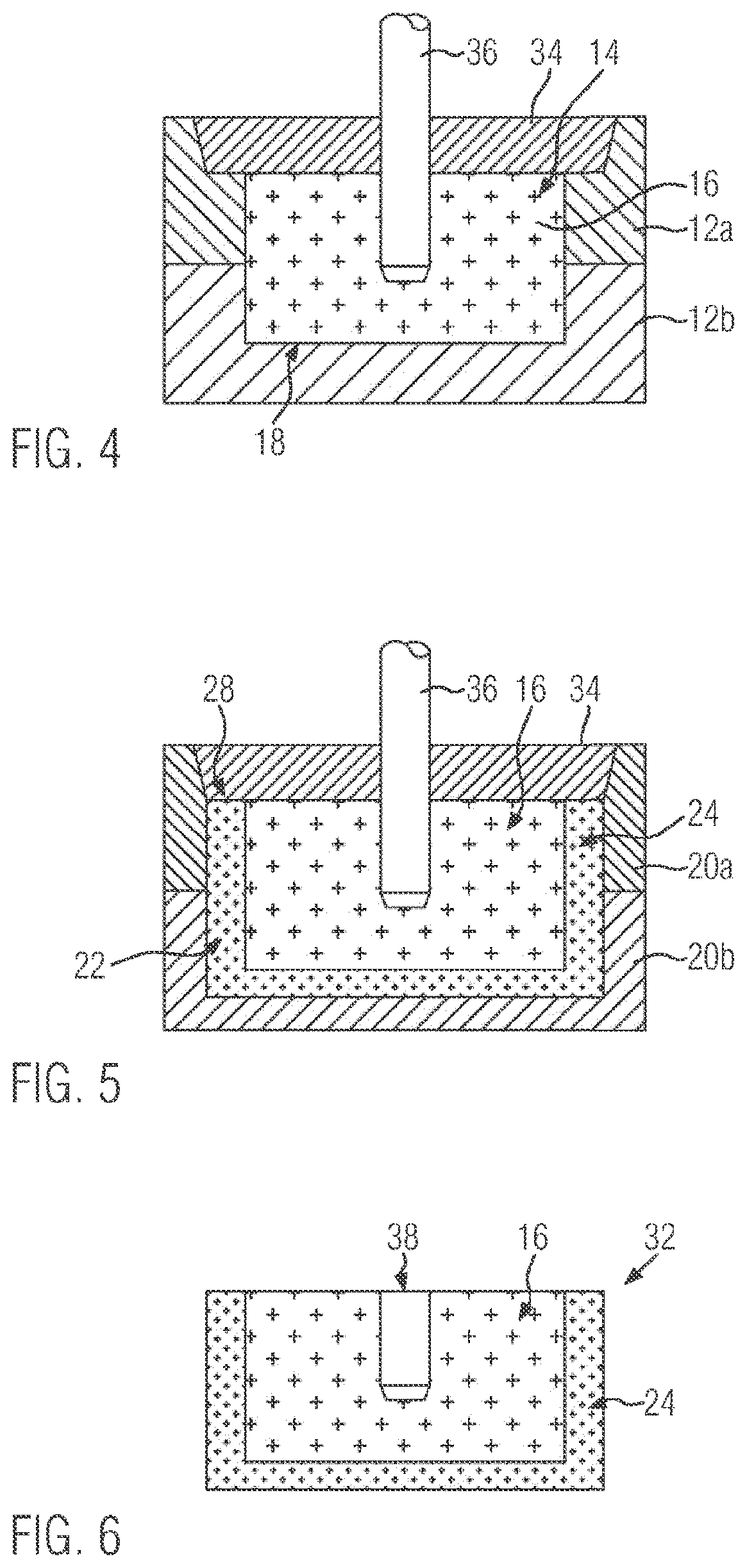
[0046]According to FIG. 5, this intermediate product 18 is transferred by displacing the pin plate 34 into the second mold cavity 22, which is dimensioned such that a free space remains between the outer surface of the intermediate product 18 and the mold cavity surfaces of the second mold cavity 22. In the present case, this free space is formed to surround the hard component 16 in the shape of a trough. Now, as in the first embodiment, foamed plastic 24 is introduced into the second mold cavity 22. The foamed plastic solidifies to form a skin, which solidifies against the surfaces bounding the second mold cavity 22. Thus, the surface penetrated by the pin 36, hereinafter referred to as the surface of the brush head 28, also exhibits a sealed surface configuration.

[0047]After ejecting the bristle carrier 32, the pin plate 34 is also removed. Instead of the pin 36, the bristle carrier 32 now has a blind hole boring 38.

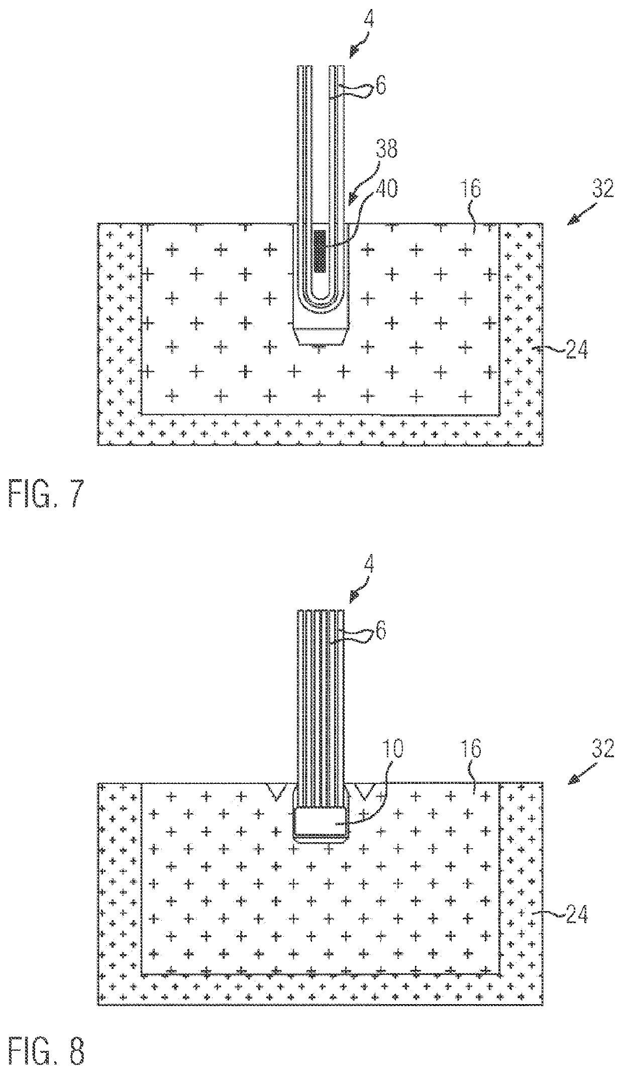
[0048]As FIG. 7 illustrates, a bristle bundle 4 may be driven int...


PUM

PropertyMeasurementUnit
tensile strengthaaaaaaaaaa

Abstract

The present invention provides a brush including a brush head (28) carrying bristle filaments (6), a brush neck and a handle stem, which are arranged one behind the other in the longitudinal direction of the brush, in which a bristle carrier (32) holding the bristle filaments (6) is formed from a hard component (16) and the handle stem is formed from a foamed plastic material (24). In a method according to the invention, a first plastic component (16) is injected into a first mold cavity (14) to form a bristle carrier (32) holding bristle filaments (6), the bristle carrier (32) is transferred to a further mold cavity (22) and, in a further molding cycle, a foaming plastic (24) is introduced into the further mold cavity (22), which foams in the further mold cavity (22).

Description

CROSS-REFERENCE TO RELATED APPLICATIONS[0001]This application is the United States national phase of International Application No. PCT / EP2020 / 058741 filed Mar. 27, 2020, and claims priority to German Patent Application No. 10 2019 204 397.6 filed Mar. 28, 2019, the disclosures of each of which are hereby incorporated by reference in their entireties.BACKGROUND OF THE INVENTIONField of the Invention[0002]The present invention relates to a brush, in particular a toothbrush, and a method of manufacturing the same.Description of Related Art[0003]A brush, in particular a toothbrush, has a brush body carrying bristle filaments. The brush body has a brush head with the bristle filaments being attached thereto, a handle stem for handling the brush, and a brush neck located therebetween.[0004]Such brushes in the form of toothbrushes have been known for a long time.[0005]EP 1 110 478 A1 originating from to the applicant relates to a method of manufacturing a toothbrush. In this process, an in...

Claims


Application Information

Patent Timeline
Patent Type & Authority Applications(United States)
IPC IPC(8): A46B3/04A46B5/02A46D3/00
CPCA46B3/04A46B2200/1066A46D3/005A46B5/021
Inventor BREITBACH, JENS
Owner M C SCHIFFER
Why Eureka
Try Eureka