Stent

a stent and stent technology, applied in the field of stents, can solve the problems of lack of flexibility, lack of flexibility, and inability to achieve the effect of radial sustaining force, and achieve the effect of more flexibility

Inactive Publication Date: 2011-07-26
KAWASUMI LABORITORIES INC
View PDF15 Cites 10 Cited by
  • Summary
  • Abstract
  • Description
  • Claims
  • Application Information

AI Technical Summary

Benefits of technology

[0009][1] A stent (1, 1A, 1B) with high bending flexibility, which has a generally tubular body formed of ring units formed of a plurality of cells each, and said tubular body is expandable in the radius direction of said tubular body from inside of said tubular body,
[0015][2] A stent (1, 1A, 1B) with high radial force and bending flexibility, which has a generally tubular body formed of ring units formed of a plurality of cells each and is expandable in the radius direction of said tubular body from inside of said tubular body,
[0025][4] The stent (1, 1A, 1B) as recited in any one of the above [1] to [3], wherein the connector portions (5, 5A, 5B) at the outer most ends of said stent 1, 1A, 1B) have a larger length or a smaller width than the connector portions (5, 5A, 5B) on the inward side of the stent 1, 1A, 1B) so that the stent has more flexibility.

Problems solved by technology

Since, however, the stent is inserted through tortuous parts of a blood vessel, along the curves of it, during expansion or delivery, the cells 206 partly project outward to be caught by the wall of the vessel, so that the delivery has been sometimes difficult (which will be referred to as “flare phenomenon” hereinafter).
However, the defect with it is that it lacks flexibility.
The conventional stents thus have the problem that they are not well-balanced in flexibility and radial sustaining force.

Method used


Image

  • Stent
  • Stent
  • Stent

Examples


example 1

[0095]For evaluating a difference in radial sustaining force depending upon an angle after expansion in a stent A(B) constituted of components 19 formed of a generally-17 and a generally-S-shaped connector portion 18 each as shown in FIG. 10, there were prepared two stents, each stent having the components 19 different in number in the circumferential direction, a stent A (number of arranged components: 8) and a stent B (number of arranged components: 6) and the stents were evaluated for radial sustaining forces and compared.

[0096]Stent A:

[0097]

Number of arranged component 198Width of strut of cells 170.12 mmThickness of strut of cells 170.10 mm1 θ angle after expansion to 3 mm60°

[0098]Stent B:

[0099]

Number of arranged component 196Width of strut of cells 170.12 mmThickness of strut of cells 170.10 mm1 θ angle after expansion to 3 mm81°

[0100]For the evaluation, each stent was expanded so as to have a diameter φ of 3 mm and placed in a silicon tube placed in a chamber, then, pressure ...

example 2

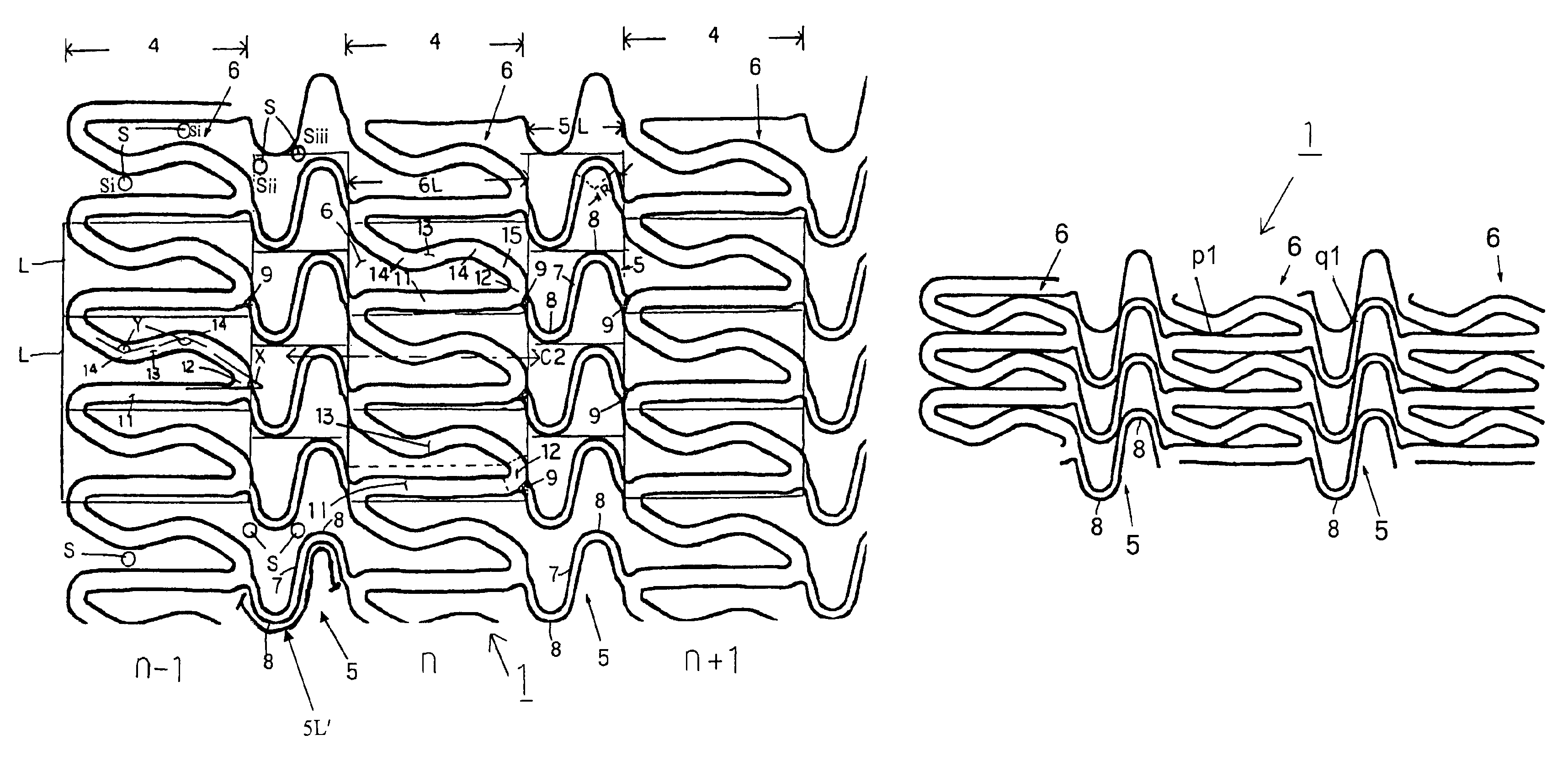
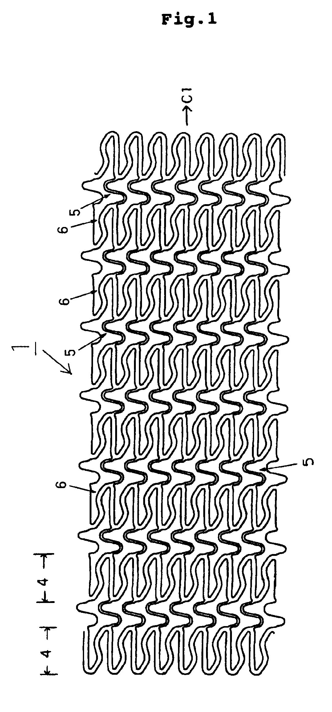
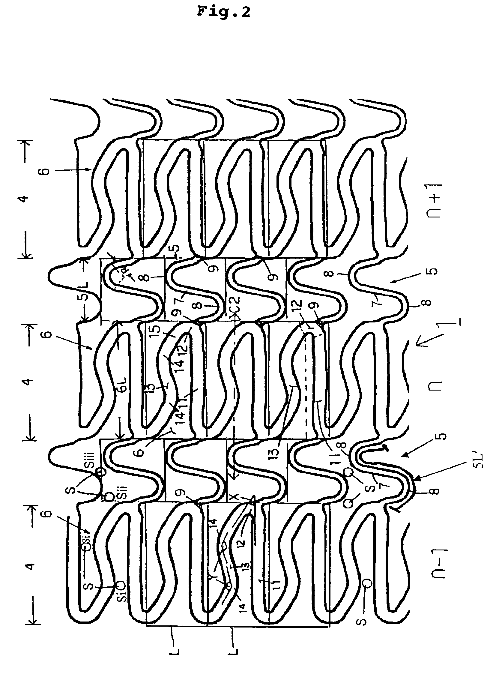
[0103]A stent shown in FIG. 1 was prepared, and the radial sustaining force thereof was compared with the counterparts of conventional stents 201 (FIG. 11) and 241 (FIG. 12). Further, the flexibility of the prepared stent was compared with that of the stent 201. In the stent 1, the ratio of the length 6L of the cell 6 in the axial direction of the stent and the length 5L of the connector portion 5 in the axial direction of the stent was determined such that on the basis that the length 6L of the cell 6 in the axial direction of the stent was taken as 100, the length 5L of the connector portion 5 in the axial direction of the stent was made 59. The stent was evaluated for a radial sustaining force in the same manner as in Example 1, and it was evaluated for flexibility by a four-point bending method. Table 2 shows the results of measurement of the radial sustaining force, and Table 3 shows the results of measurement of the flexibility.

[0104]

TABLE 2(Results of measurement of radial su...

example 3

[0107]A stent 1A shown in FIG. 6 (FIG. 7) and a stent 1B shown in FIG. 8 (FIG. 9) were measured and evaluated for radial sustaining forces and flexibility in the same manner as in Examples 1 and 2. In the stent 1A or the stent 1B, the ratio of the length 6AL, 6BL of the cell 6A, 6B in the axial direction of the stent and the length 5AL, 5BL of the connector portion 5A, 5B in the axial direction of the stent was determined and formed such that on the basis that the length 6AL, 6BL of the cell 6A, 6B in the axial direction of the stent was taken as 100, the length 5AL, 5BL of the connector portion 5A, 5B in the axial direction of the stent was 59. Table 4 shows the results of measurement of the radial sustaining force, and Table 5 shows the results of measurement of the flexibility. As is clear from Tables, it has been shown that the stent 1A and the stent 1B give substantially the same results as those of the stent 1.

[0108]

TABLE 4(Results of measurement of radial sustaining force)Ste...


PUM


Abstract

A stent having a generally tubular body formed of ring units formed of a plurality of cells each and expandable in the radial direction, wherein each ring unit is constituted of cells connected to one another above and below, arranged to surround the center line of the stent, the ring units are arranged in the axial direction of the stent, and are connected with connector portions, each connector portion is formed of curved portions each having an arch and a generally linear portion continued thereto, 3 to 8 cells are arranged in the axial direction per 10 mm of the length of the stent, and the ratio of the length of the cell in the axial direction and the length of the connector portion is determined such that on the basis that when the length of the cell is 100, that of the connector portion 50 to 100, thereby securing flexibility and radial sustaining force.

Description

TECHNICAL FIELD[0001]The present invention relates to improvements in a stent used for amelioration of a stenosed portion that occurs in an organism such as a blood vessel.TECHNICAL BACKGROUND[0002]A stent refers to a tubular medical tool that is placed in a stenosed portion or the like for dilating the stenosed portion, etc., to secure a necessary lumen region when a blood vessel or a lumen in an organism is stenosed or occluded. The stent is inserted into a body with its diameter kept small, and is expanded in a stenosed portion, etc., to have a larger diameter so that the above lumen is dilated and sustained.[0003]Conventional stents are typically as shown in FIGS. 11 and 12. However, these have had the following drawbacks. FIG. 11A and FIG. 12A show stents before expansion, and FIG. 11B and FIG. 12B show the stents after expansion.[0004]In a stent 201 shown in FIG. 11, cells 206 constituting a ring unit 204 have a structure in which three linear portions 207 are connected in par...

Claims


Application Information

Patent Timeline
Patent Type & Authority Patents(United States)
IPC IPC(8): A61F2/06A61F2/915A61M29/02
CPCA61F2/91A61F2/915A61F2002/91533A61F2002/91558A61F2002/91575A61M29/02
Inventor IKEUCHI, KENMORI, KOUJIIWATA, HIROOMITSUDOU, KAZUAKINOMIYAMA, HIROAKIYOSHIKAWA, YOSHIHARUWATANABE, MASATOSHIYAMASHITA, SHUZOUMURAKAMI, KAZUNORI
Owner KAWASUMI LABORITORIES INC
Why Eureka
Try Eureka