Light-emitting apparatus and production method thereof

a technology of light-emitting apparatus and production method, which is applied in the direction of electrical apparatus, semiconductor/solid-state device manufacturing, and semiconductor devices, etc., can solve the problems of reducing production yield, affecting the production efficiency of light-emitting medium, and not yet solving the above-mentioned problem, so as to achieve more secure conduction and suppress the damage of the light-emitting medium

Active Publication Date: 2011-07-26
CANON KK
View PDF14 Cites 5 Cited by
  • Summary
  • Abstract
  • Description
  • Claims
  • Application Information

AI Technical Summary

Benefits of technology

[0013]The present invention provides a light-emitting apparatus which can prevent a shadow mask from contacting a light-emitting medium to thereby suppress a damage of the light-emitting medium, by using a conductive layer formed on a device isolation layer as a pressing member for the shadow mask, and at the same time, can attain more secure conduction between a second electrode and an auxiliary electrode.
[0016]According to the present invention, the conductive layer reaches an upper end planarizing portion of the device isolation layer, and the thickness of this upper end planarizing portion is formed thicker than the distance between the first electrode and the second electrode in a light-emitting region. The light-emitting medium is deposited by pressing the shadow mask on the conductive layer, so that no damage is given to the light-emitting medium and the production yield can be improved. Further, the light-emitting medium is deposited by pressing the shadow mask on the conductive layer, so that the second electrode and the auxiliary electrode can be more securely in electrical conduction.

Problems solved by technology

However, there has been a problem that at that time, the thus formed organic layers are damaged by the shadow masks to reduce the production yield.
However, although the display apparatus and the production method thereof as proposed in Japanese Patent Application Laid-Open No. 2002-318556 are configured to be capable of preventing the voltage drop of the second electrode, the above described problem is not yet solved.
Further, in the light-emitting apparatus and the production method as proposed in Japanese Patent Application Laid-Open No. 2003-316291, since the film deposition of the organic light-emitting medium is performed without bringing the mask into contact the substrate side, there are problems such that the film thickness of each pixel varies and a shift of the alignment is produced due to the bending of the mask.
Further, there are also the problems that a film of the organic light-emitting medium is deposited on the auxiliary electrode to interrupt the electrical conduction between the auxiliary electrode and the second electrode, or the resistance value increases due to the organic light-emitting medium, so that the function as the auxiliary electrode cannot sufficiently be exhibited.

Method used


Image

  • Light-emitting apparatus and production method thereof
  • Light-emitting apparatus and production method thereof
  • Light-emitting apparatus and production method thereof

Examples


Embodiment Construction

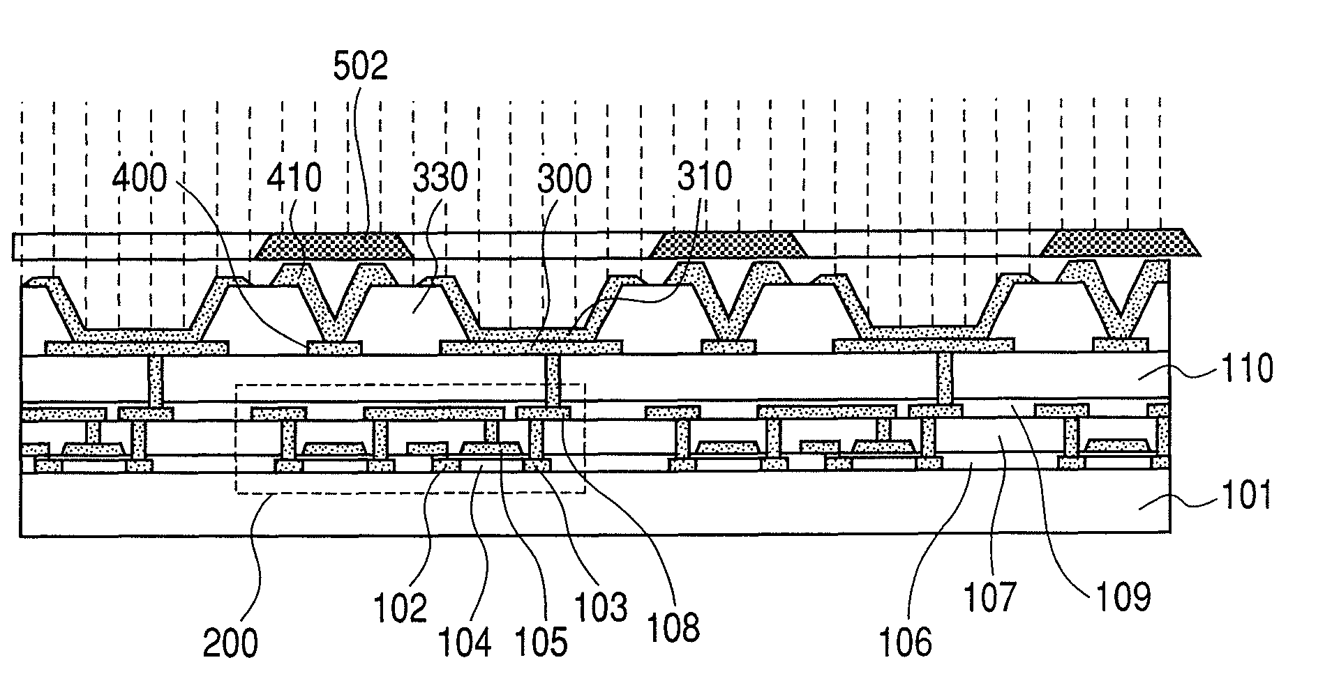
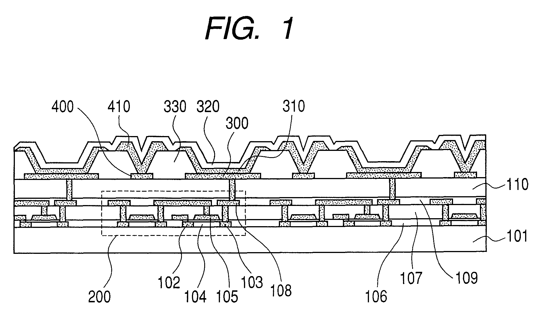
[0027]The light-emitting apparatus according to the present invention includes a plurality of light-emitting devices each including a first electrode, a light-emitting medium, and a second electrode in the mentioned order on a substrate, a device isolation layer formed between the plurality of light-emitting devices and defining the respective light-emitting devices, and an auxiliary electrode formed between the substrate and the device isolation layer.

[0028]Hereinafter, an embodiment of a light-emitting apparatus and its production method according to the present invention will be described in detail with reference to the drawings. However, the present invention is not limited to the present embodiment.

[0029]First, a production method of the light-emitting apparatus will be described.

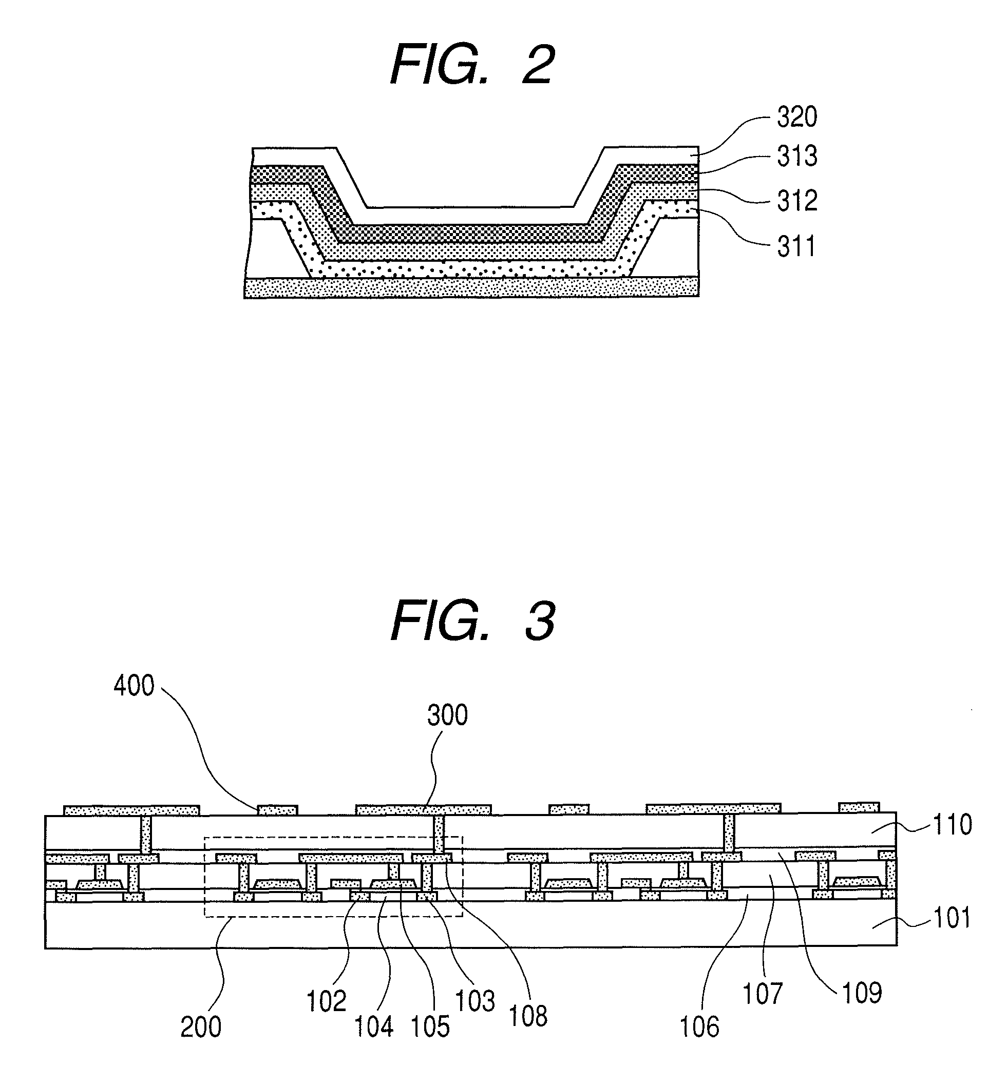
[0030]As shown in FIG. 3, on a substrate 101 such as a glass substrate, TFTs 200 are formed. In the figure, reference numeral 102 denotes a source region, reference numeral 103 a drain region, referenc...


PUM


Abstract

Provided is a light-emitting apparatus which can prevent a shadow mask from contacting a light-emitting medium to suppress damage of the medium, by using a conductive layer formed on a device isolation layer as a pressing member for the shadow mask, and can attain more secure conduction between a second electrode and an auxiliary electrode. A production method of the light-emitting apparatus includes forming first electrodes and auxiliary electrodes on a substrate; forming a device isolation layer between the first electrodes and forming an opening on each of the first electrodes and the auxiliary electrodes; forming a conductive layer on the device isolation layer so as to cover the openings above the auxiliary electrodes; bringing a shadow mask into contact with the conductive layer and forming a light-emitting medium in a thickness smaller than the thickness of the conductive layer; and forming a second electrode so as to cover the light-emitting medium, the device isolation layer, and the conductive layer.

Description

BACKGROUND OF THE INVENTION[0001]1. Field of the Invention[0002]The present invention belongs to the field of technology of a light-emitting apparatus including a light-emitting device and a production method thereof.[0003]2. Description of the Related Art[0004]An organic electroluminescent device utilizing electroluminescence (hereinafter, simply referred to as EL) of an organic material has attracted attention as a light-emitting device which can emit light at a high luminance by low-voltage driving.[0005]A display apparatus of an active matrix type using such an organic EL device (i.e., organic EL display) is provided with a thin film transistor (hereinafter, simply referred to as TFT) in each of pixels formed on a substrate. The organic EL device is formed on an interlayer insulating film formed so as to cover the TFTs.[0006]The organic EL device has a first electrode patterned for each of the pixels in a state of being connected to the TFTs and an insulating device isolation la...

Claims


Application Information

Patent Timeline
Patent Type & Authority Patents(United States)
IPC IPC(8): H01L31/12H01L21/00
CPCH01L51/5203H01L27/3244H01L27/3295H10K59/122H10K59/12H10K59/805H10K50/805
Inventor ITO, NAOYUKI
Owner CANON KK
Why Eureka
Try Eureka