Construction machine

a construction machine and construction technology, applied in soil shifting machines/dredgers, roofs, transportation and packaging, etc., can solve the problems of deterioration of outer appearance, difficulty in applying the technique, and lateral visibility of operators in the cabin, so as to quickly respond to the needs of users and improve manufacturing efficiency

Inactive Publication Date: 2011-08-02
KOBELCO CONSTR MASCH CO LTD
View PDF15 Cites 17 Cited by
  • Summary
  • Abstract
  • Description
  • Claims
  • Application Information

AI Technical Summary

Benefits of technology

According to the present invention, the fuel supply unit is provided in the space which is the height difference between the fixed footboard in the standard specifications without the fuel supply unit and the fixed footboard in the special specifications with the fuel supply unit, and the steps are supported by the bracket through the fuel supply unit. Therefore, the following effects can be obtained.
Therefore, conversion can be small scale with low cost and the installation space for the devices is not invaded (the present invention can be easily applied to a small type machine).
That is, it is possible to install the fuel supply unit while solving the problems of the technique according to Patent Document 1 and avoiding the adverse effects generated when the techniques described in Patent Documents 2 and 3 are used.
In this case, since the fixed footboard also serves as the lid, it is possible to easily perform take-in and take-out or the like of the hose of the fuel supply unit installed on the lower side of the footboard from the directly upper side.
In this case, the highest footboard which is the closest to the rear part of the upper rotating body in which the fuel tank is installed serves as the fixed footboard, and the fuel supply unit is provided on the lower side of the footboard. Therefore it is possible to arrange the fuel supply unit approaching to the fuel tank at maximum. Consequently, it is easy to treat the hose and perform the take-out and the take-in of the hose.
In this case, the fuel supply unit is attached on the fixed footboard in the standard specifications, and the fixed footboard in the special specifications is attached on the fuel supply unit so as to form the steps of the special specifications. In other words, the specifications are changed by selection on whether or not the footboards are added to the steps of the standard specifications. Therefore, it is possible to quickly respond to a need of users and improve a manufacturing efficiency.

Problems solved by technology

However, in the technique of Patent Document 1, since there is a need for ensuring an installation space which is exclusive to the fuel supply unit on the upper frame, it is difficult to apply the technique particularly to a small sized excavator which does not have an extra space.
However, when the fuel supply unit is installed on the top part of the steps, the fuel supply unit protrudes to the upper side of the top part of the steps so that lateral visibility from an operator in the cabin is deteriorated and outer appearance is also deteriorated.
Consequently, conversion becomes large scale and cost is increased.
When the height of the entire footboards is increased, a position of an upper end of the steps becomes higher so that the visibility from the inside of the cabin and the outer appearance are deteriorated.

Method used


Image

  • Construction machine
  • Construction machine
  • Construction machine

Examples


first embodiment

Refer to FIGS. 1 to 6

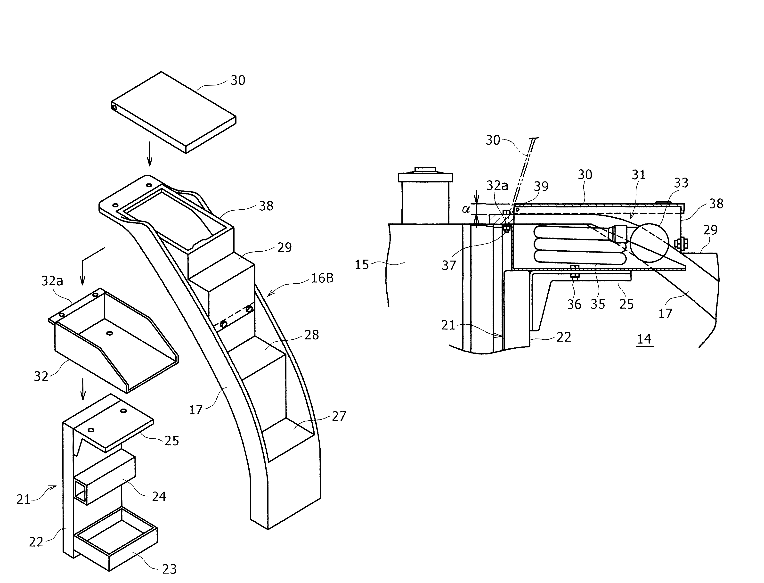
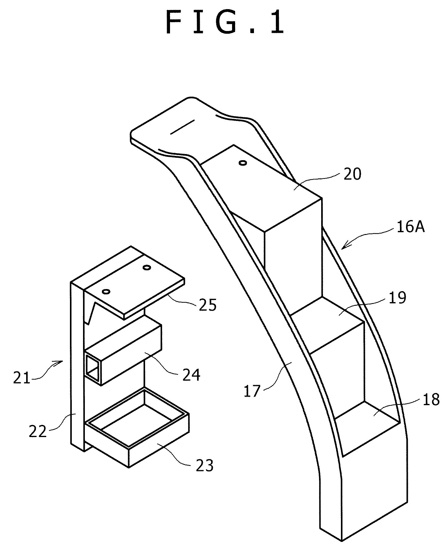
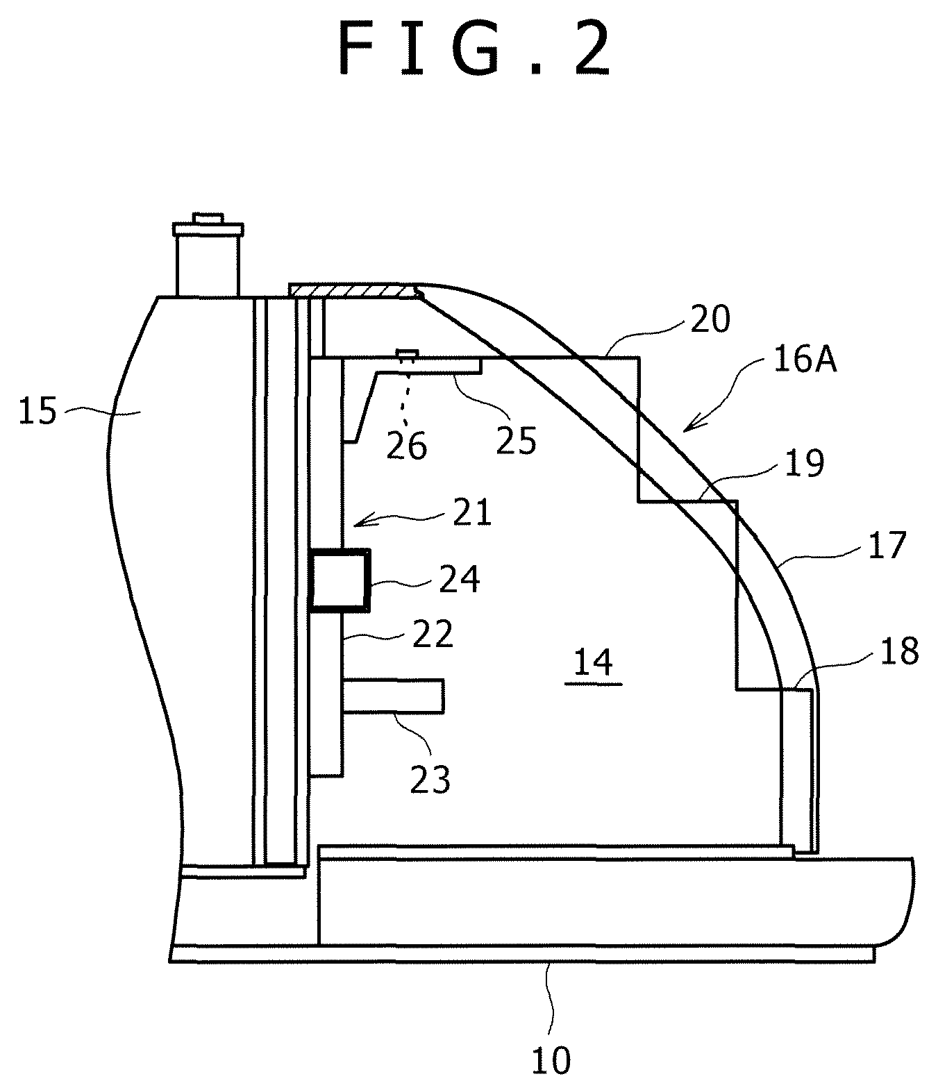
FIGS. 1 and 2 show steps 16A of standard specifications which is not provided with a fuel supply unit and related parts thereof. FIGS. 3 to 6 show steps 16B of special specifications which is provided with a fuel supply unit and related parts thereof.

The steps 16A of the standard specifications are formed by attaching a plurality of footboards 18, 19 and 20 (in an example of the figure, there are three steps in total which are a first step, a second step and a third step from the bottom, hereinafter, a description will be given on the basis of this case) to a thin and long step framework 17 in a substantially picture frame shape.

In a device chamber 14 whose upper surface is covered by the steps 16A and 16B, a bracket 21 is provided on a rear part thereof serving as a shared part for supporting the steps 16A and 16B in both the specifications from the lower side.

The bracket 21 is formed such that to a bracket main body 22, are attached a tool box 23, a pin guide ...

second embodiment

Refer to FIG. 7

Different points from the first embodiment will only be described.

In the first embodiment, the third footboard 29 and the fourth footboard 30 are provided instead of the highest footboard 20 of the standard steps 16A, while in a second embodiment, the highest footboard 20 of the standard steps 16A is directly used and the case 32 of the fuel supply unit 31 is attached to an upper surface of the footboard 20.

In this case, the footboard 20 and the case 32 may be attached to the step supporting portion 25 of the bracket 21 at the same time. Only the footboard 20 may be attached to the step supporting portion 25 and then the case 32 may be separately attached to the footboard 20.

In an example of the figure, to a step framework attachment portion 20a extending rearward at a rear end of the footboard 20 is attached the upper end part of the step framework 17. However, as in the first embodiment, the upper end part of the step framework 17 is attached to the step framework a...


PUM


Abstract

A highest footboard of steps serving as an up and down passage provided on the laterally opposite side to a cabin in an upper rotating body is located at a higher position than a highest footboard of steps of standard specifications. In a space which is height difference between the highest footboards, a fuel supply unit is installed. The steps are supported by a step supporting portion of a bracket provided in a device chamber through the fuel supply unit.

Description

BACKGROUND OF THE INVENTION1. Field of the InventionThe present invention relates to a construction machine provided with a fuel supply unit for fueling a fuel tank.2. Description of the Related ArtTHE RELATED ART will be described taking a hydraulic excavator of a preferred example of the present invention as an example.In the hydraulic excavator, as shown in FIGS. 8 and 9, an upper rotating body 2 is rotatably mounted on a crawler type lower traveling body 1 around a vertical axis. On a front part of the upper rotating body 2, is attached a working attachment 9 provided with a boom 3, an arm 4, a bucket 5, and hydraulic cylinders (boom cylinder, arm cylinder and bucket cylinder) 6, 7 and 8 for operating the boom 3, the arm 4 and the bucket 5.A cabin 11 is installed on one of left and right sides of an upper frame 10 provided in the upper rotating body 2 (in general, on the left side seen from the rear side, hereinafter a description will be given in this example).A side cover 12 i...

Claims


Application Information

Patent Timeline
Patent Type & Authority Patents(United States)
IPC IPC(8): B62D25/22B62D25/24
CPCB60R3/00E02F9/0833
Inventor SAKITANI, SHINTAROWATANABE, SACHIKO
Owner KOBELCO CONSTR MASCH CO LTD
Why Eureka
Try Eureka